Fusion 360
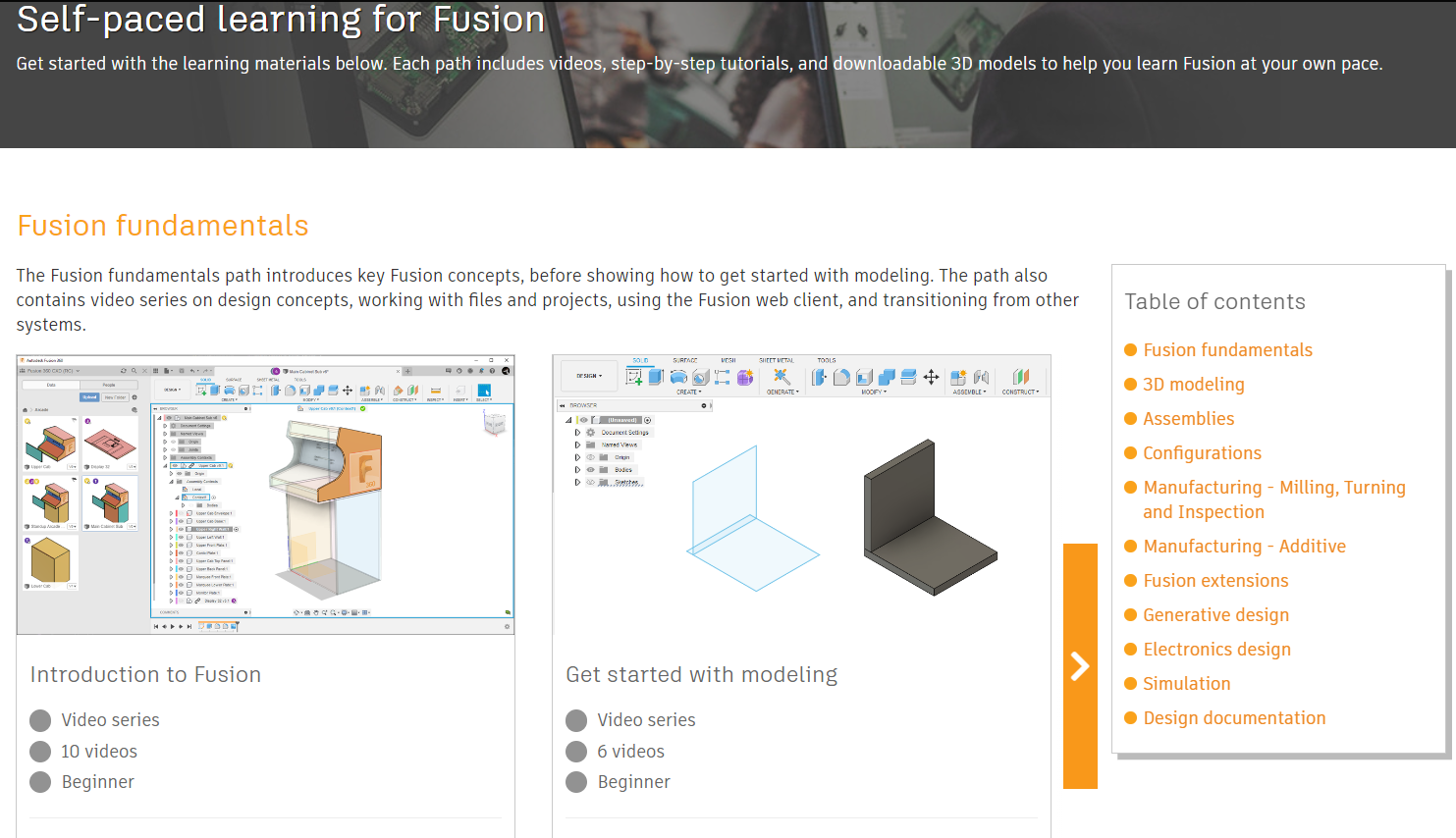
Fusion Help | Self-paced learning for Fusion | Autodesk
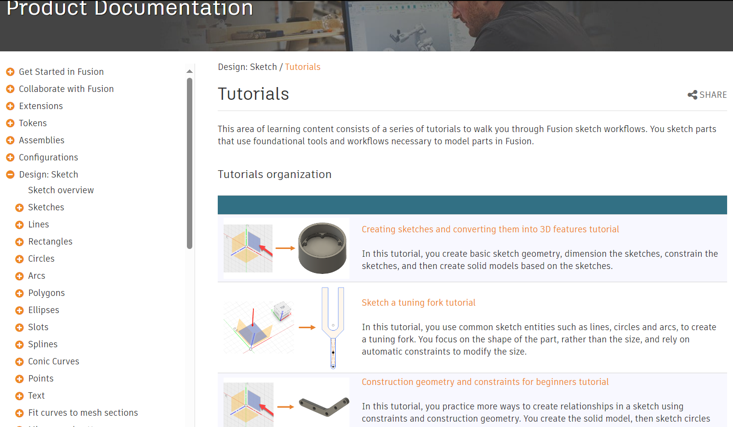
Fusion Help | Tutorials | Autodesk
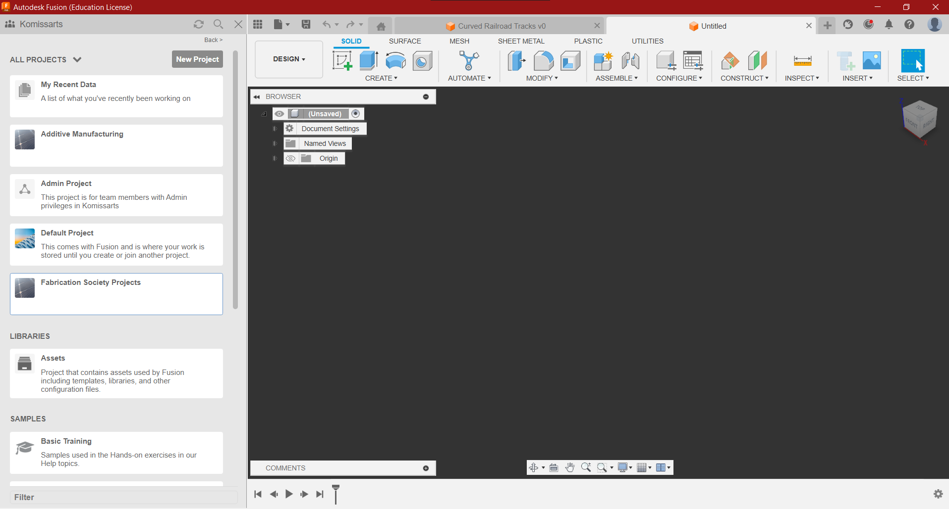
Home Screen Overview
- Left - Teams you are in, Project Files & Folders
- Right - Blank Workspace
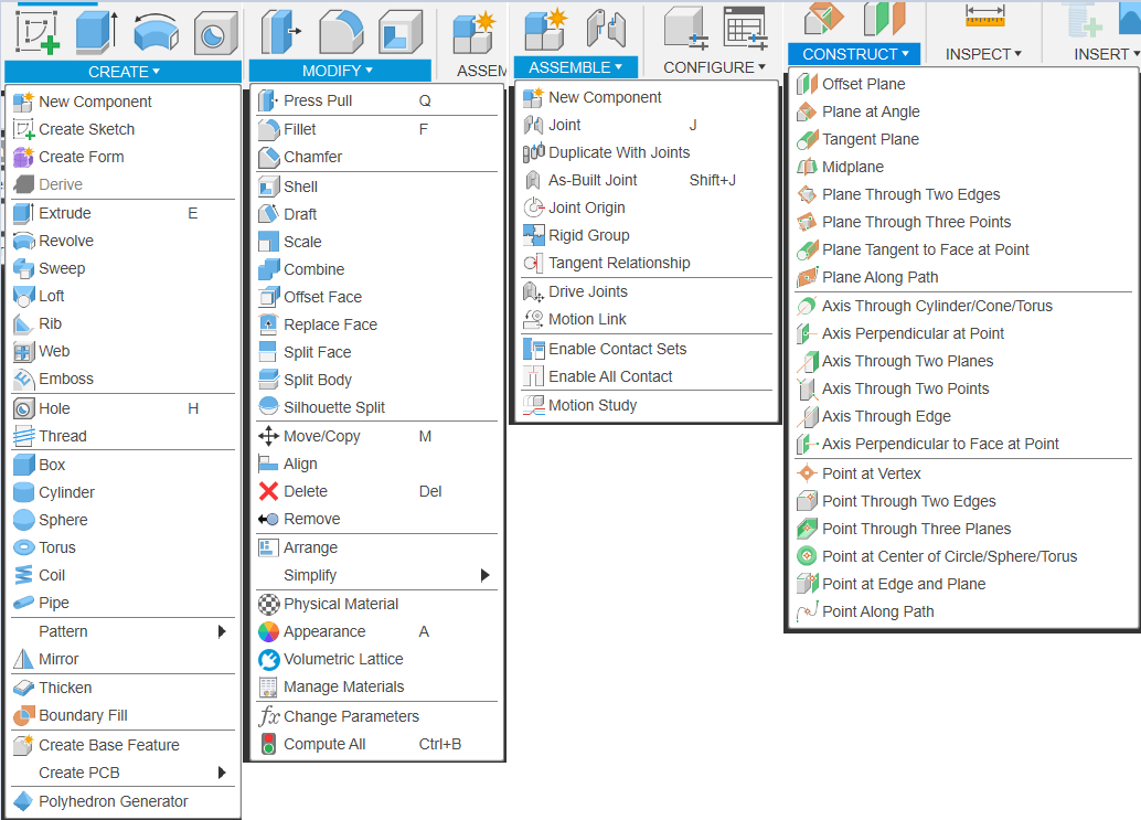
Object Modification Tools
Making A Train & Tracks
- By Now you should have created your own private Team, Create a New Project Labelled “CAD Workshops”
- Create a new Folder Labelled “Workshop 1: Train & Tracks”
Making Curved Train Tracks
Create New Component and…
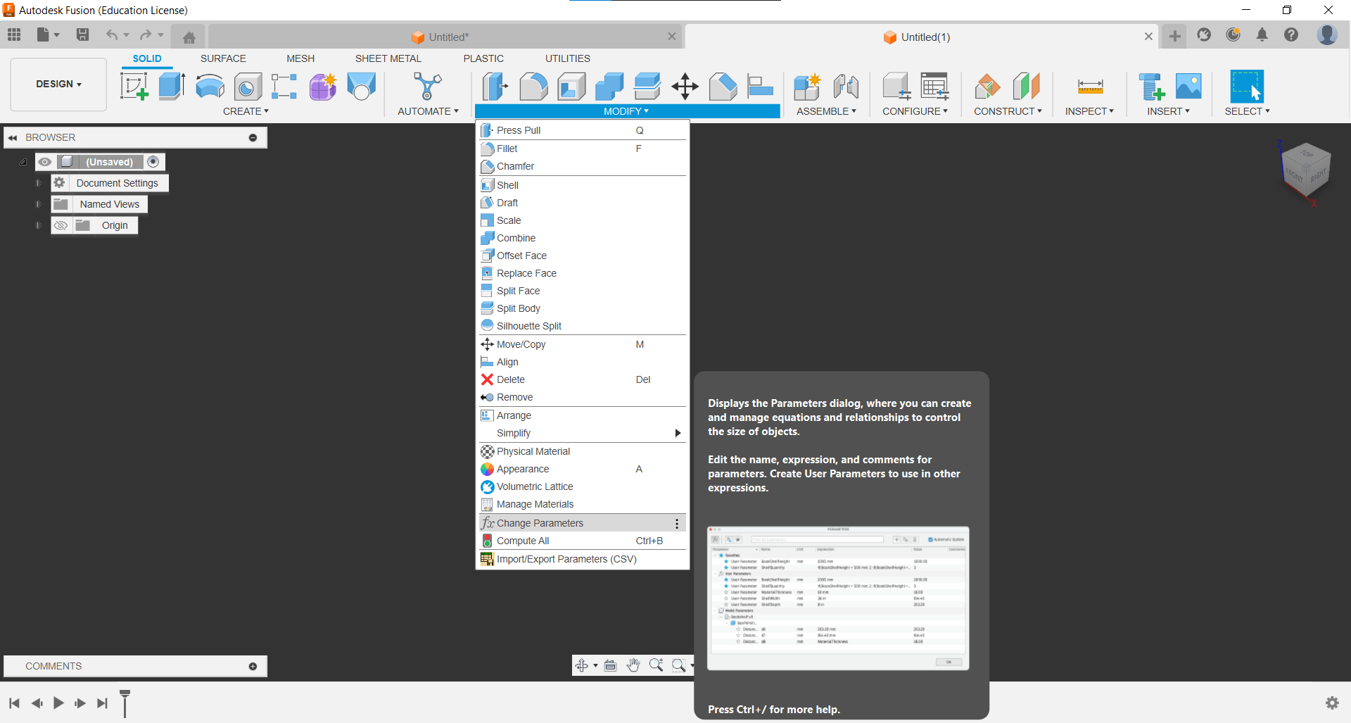
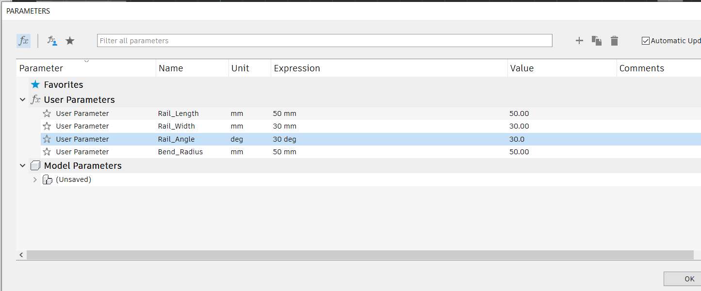
Set Parameters
- Create new parameters for the Rail Length, Width, Bend Radius & the Angle.
- by default, the unit is mm, but you’ll have to change the unit to deg. for the angle
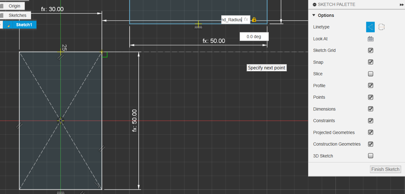
Create New Sketch
- set the dimensions for the sketch to be the parameters we’ve just set
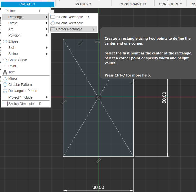
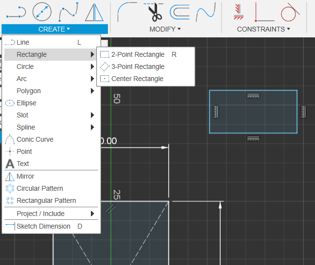
Add 2 Point Rectangle Floating Nearby
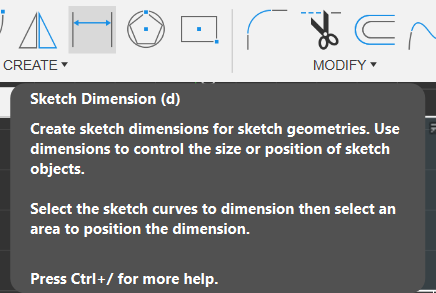
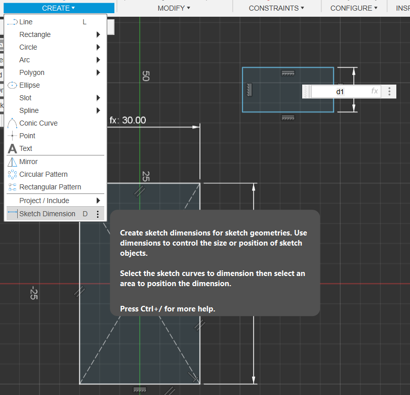
Use Sketch Dimension and ctrl click on existing dimensions
- You can click and drag the new rectangle to adjust it’s position
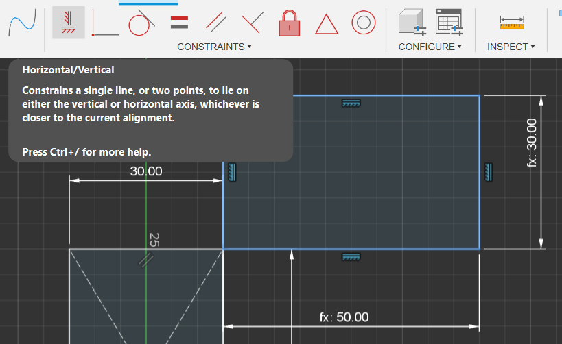
Delete New Rectangle’s Horizontal & Vertical Constraints
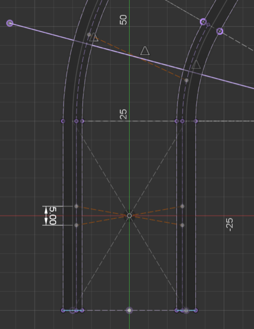
Create Extending line, (Bend Radius) Perpindicular to 1st Rectangle, as a Construction line
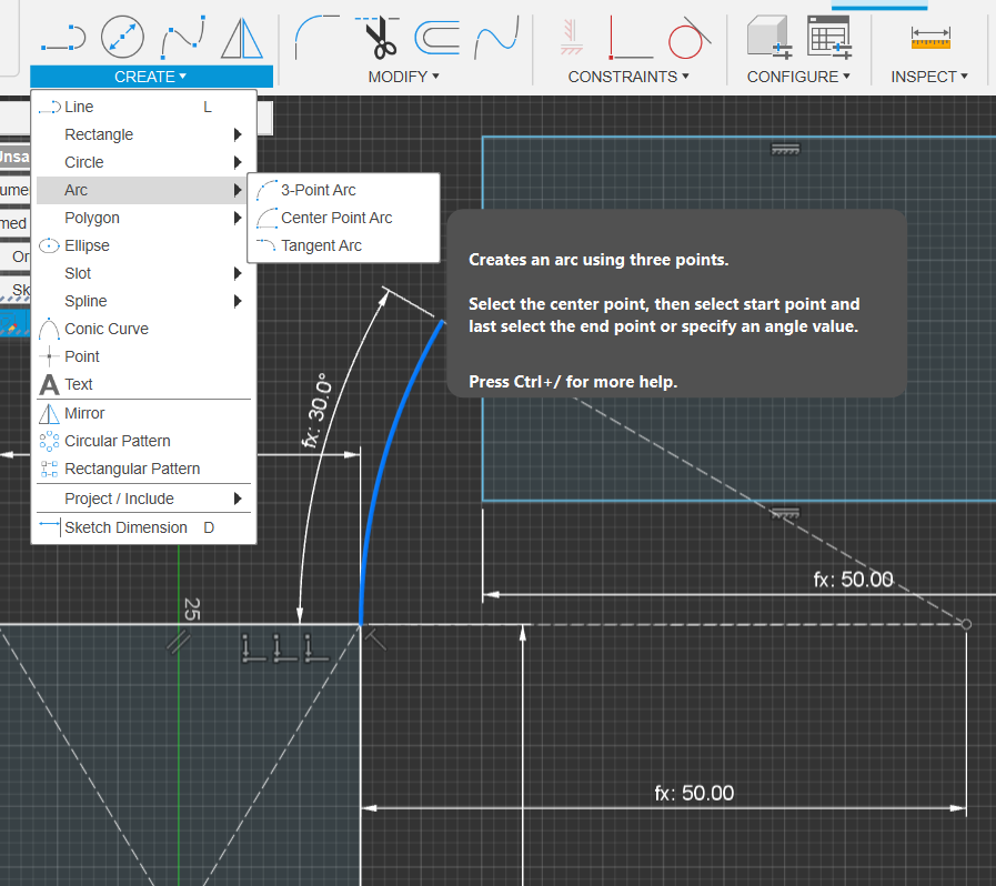
Create Center Point arc
(RailAngle) from the end of Bend Radius to Inner corner of the 1st Rectangle
Repeat For Outer Edge
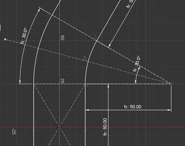
Use Coincident Constrain to attach bottom left of the 2nd Rectangle to the inner Curve modifier.
- Then do the same for the outer edge
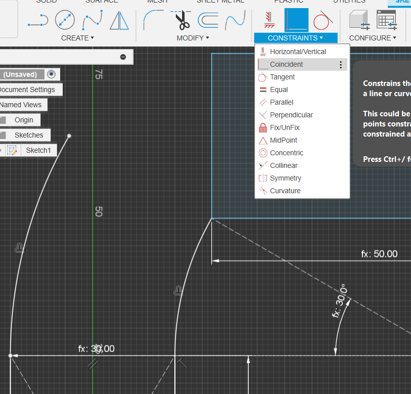
Difference Between Free Floating Sketches & Dimensioned Sketches
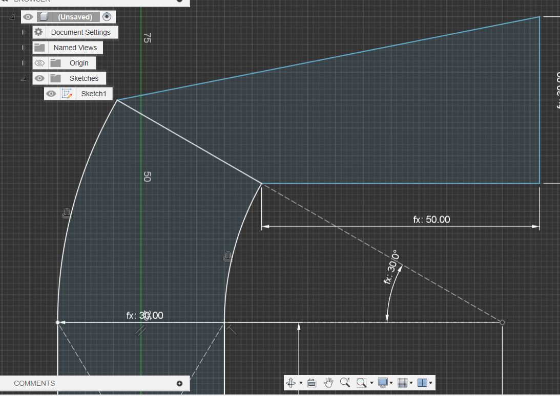
- Blue Lines: Not Dimensioned
- White Lines: Is Dimensioned
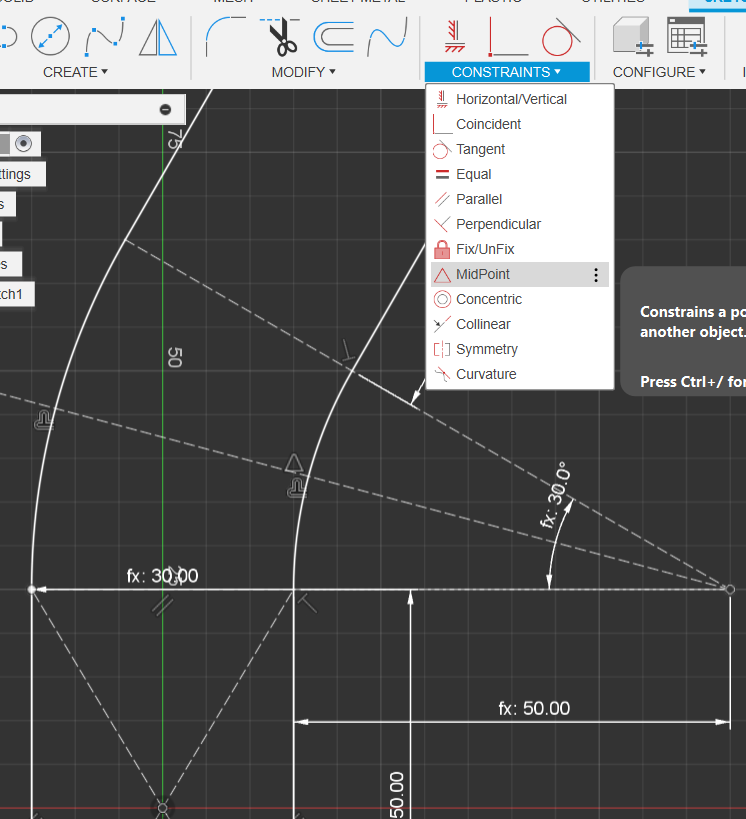
Dimensioning The Sketch
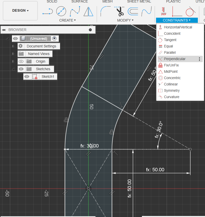
- Constrain the long Edges to be parallel & one of the sides and bottom lines to be perpendicular
- You will now notice that the sketch has a red lock
Turn All Solid Lines (except the outer rail lines) into construction lines
- Select All and press X (or select Construction Linetype)
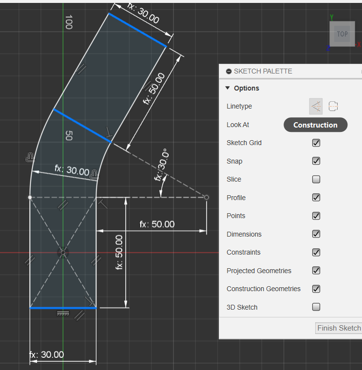
Create Construction line attached to the midpoint of the curved bend
- (This will act as our mirror line when we duplicate the connection bars between the rails)
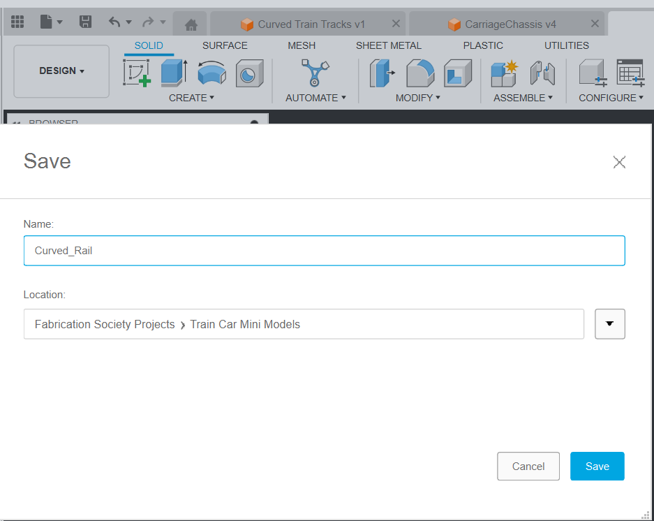
Finish Sketch, and Rename to Curved Rail, & Save to your Train & Rail Project Folder
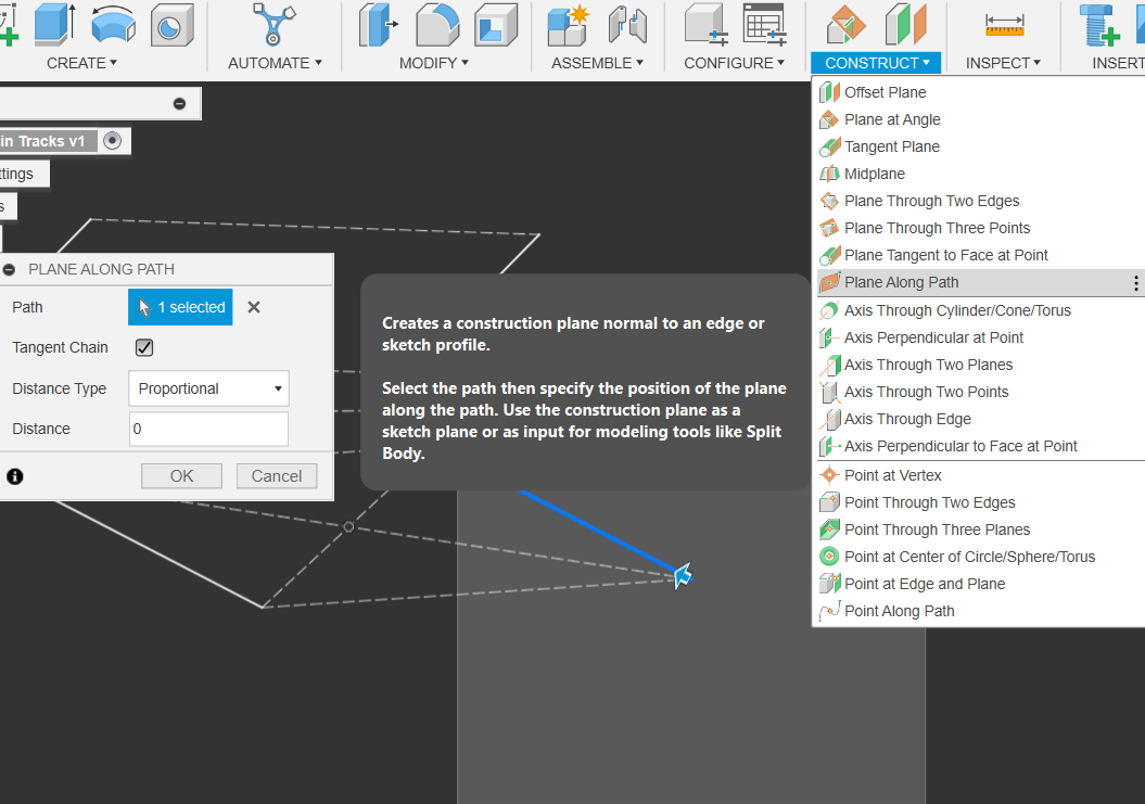
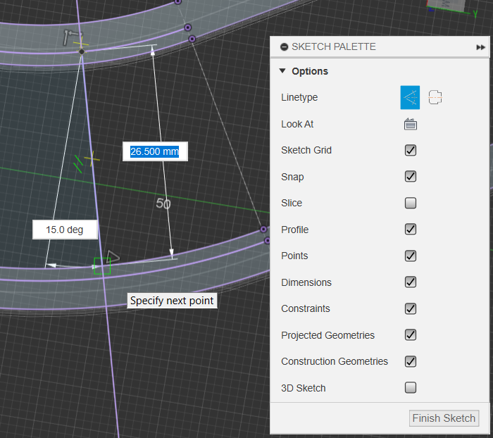
Create Plane Along Path of outer rail
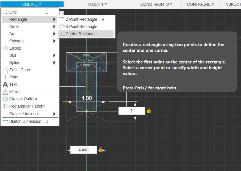
Start new Sketch & Design Steel Girders using Center Rectangle
- Feel free to make your own custom design too if you’d like!
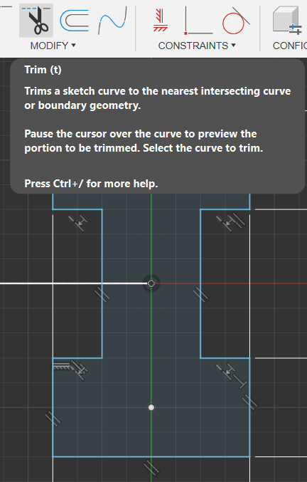
Select & Delete Construction Lines & Trim Overlap
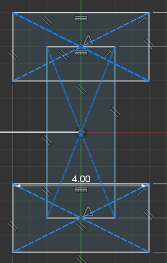
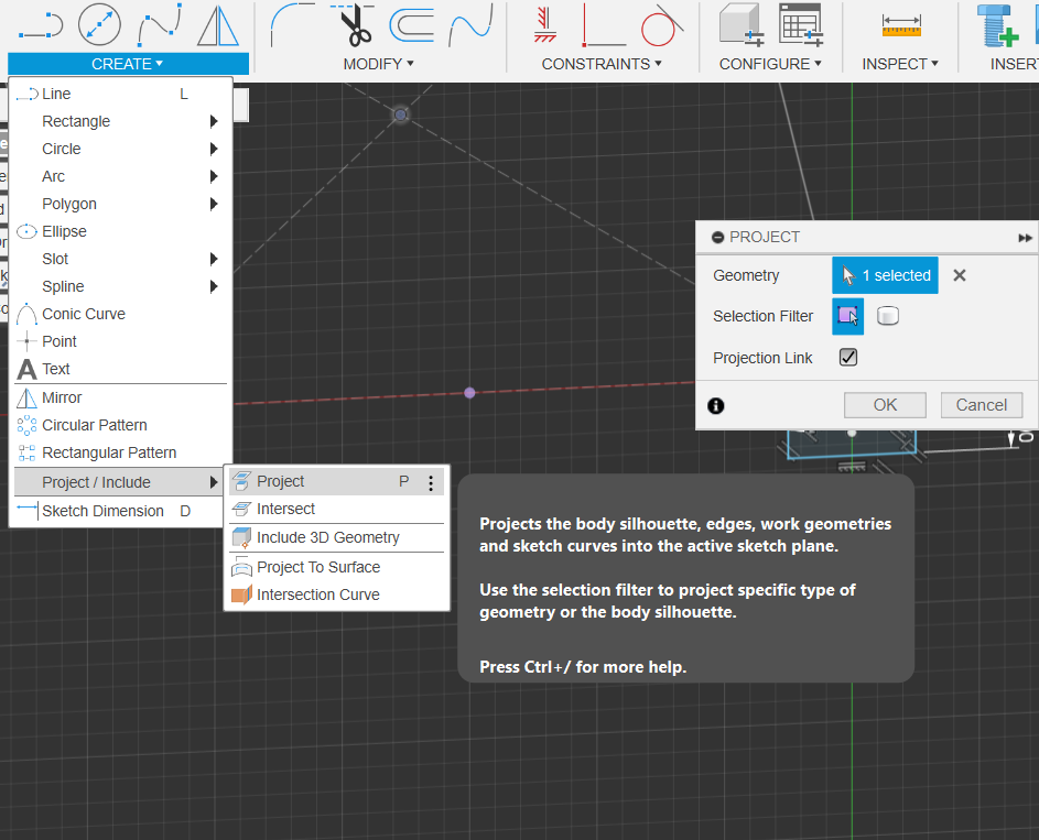
Project the Midpoint of the 1st Rectangle to the current Sketch
- This gives us reference to the midpoint, allowing us to mirror the design across.
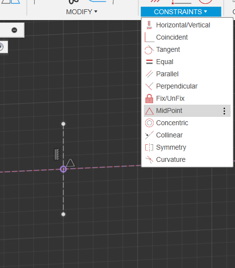
Create a Vertical Floating Construction Line & Constrain it to the new points’ midpoint
Select the Mirror Tool, Double click the Rail Object & select the newly created middle line as Mirror Line
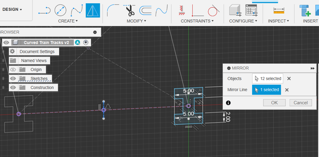
Finish, Rename (RailSketch) & Save
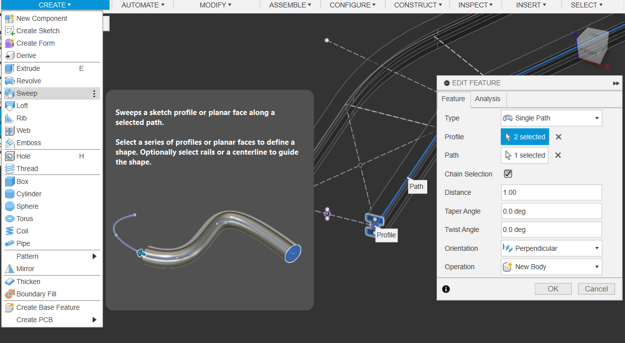
Perform Sweep Command using the Rail Sketch & the Rail Path
- make Sure Chain Selection is turned on (this just auto selects any connecting paths, as our rail is technically made of 3 separate paths)
- (You can select both profiles we made & the paths should auto fill!)
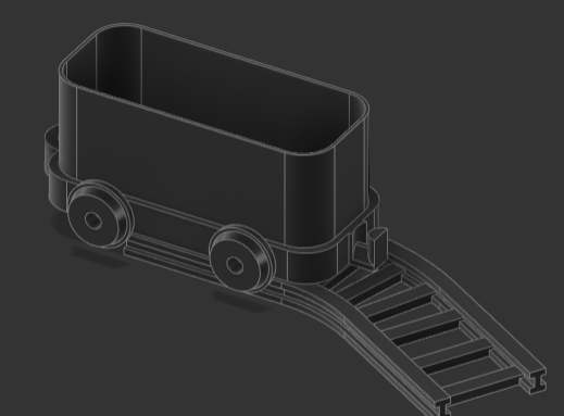
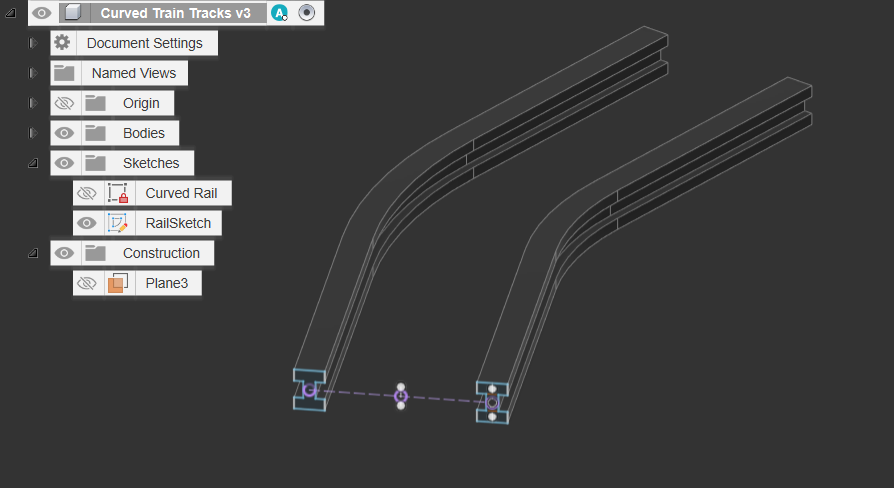
Congrats, You should now have a rail path!
Now to design the Sleepers…
- Create an Offset plane & set the offset to 0
- Create a new sketch, and project the bottom, Inner Plane & the midplane we made during the rail sketch!
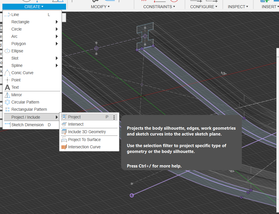
Select & Set these new Projection Lines as Construction Lines
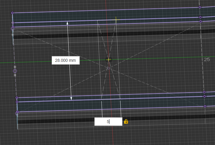
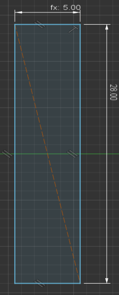
Create Sleepers using Centre Rectangle at the Midpoint
- atm, I used 28x5mm for the sleepers, although you are welcome touse the line and curve tools to make your own custom designs!
- DONT FORGET TO CONSTRAIN THE FAR EDGES OF THE SLEEPERS TO THE RAIL
Create Line Tracing the Middle line we used earlier! Ensure it is set as Construction & USE THE FIX/UNFIX Constraint to keep it in place
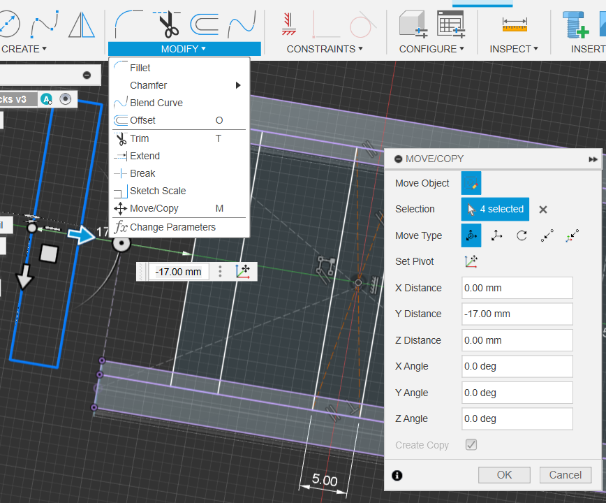
Use Move Command to Create Copy of a sleeper
- Use the Move/Copy Command (FIRST CLICK CREATE COPY CHECKBOX)
- Then just move it out of the way, distance does not matter, as we’ll be constraining it to the curved mid-line
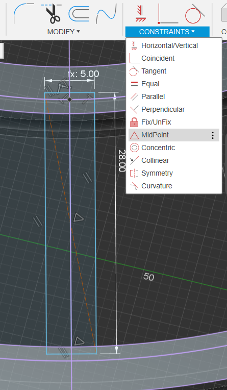
Add Construction Line to find it’s center point, Dimension Sides, Pareallel & Perpendicular Constrain the sides and Corners
Midpoint & Perpendicular Constrain it to the middle Line
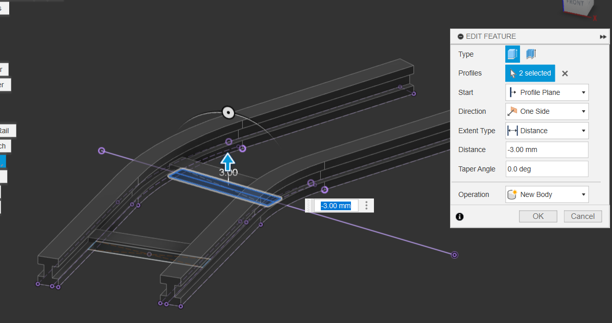
Extrude The Straight Rail Sleeper & Curved Rail Sleeper
- Select the Sleepers & Extrude them by 3mm
- Extrude as separate “extrude” actions, we want them as separate “features”
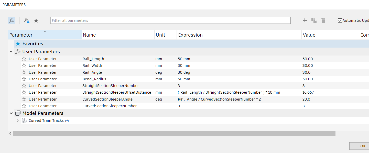
Create More Parameters!!!
- Create the Following new parameters:
- StraightSectionSleeperNumber: 3
- StraightSectionSleeperOffsetDistance: (Rail_Length/StraightSectionSleeperNumber) * 10mm
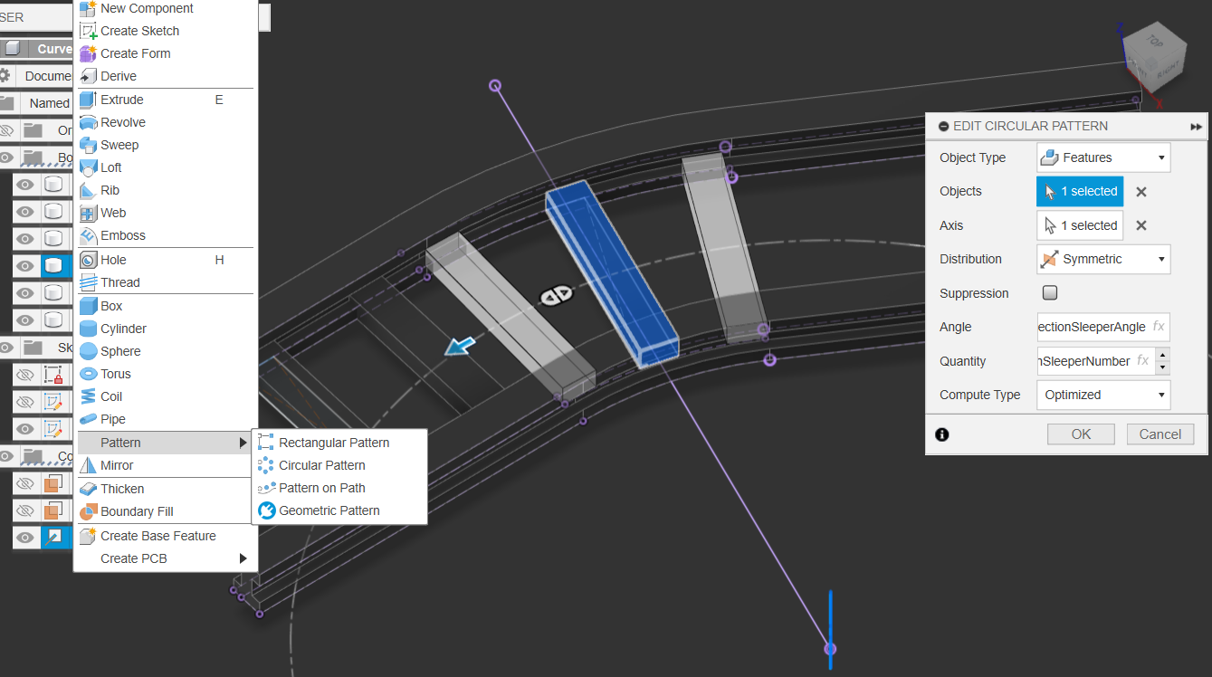
- CurvedSectionSleeperAngle: Rail_Angle / CurvedSectionSleeperNumber * 2
- CurvedSectionSleeperNumber: 3
Pattern The FEATURE, Not the SKETCH or BODY
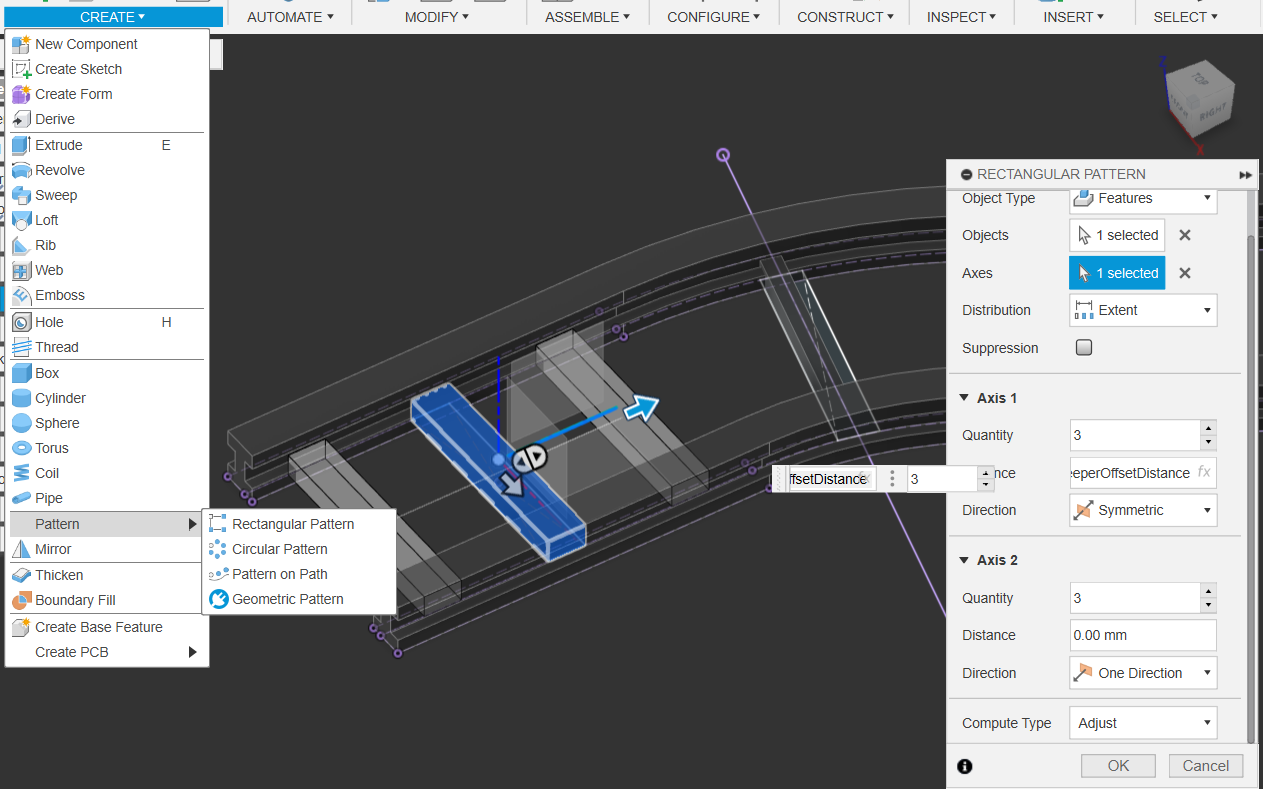
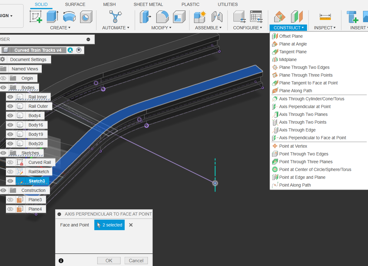
Pattern the Curved Sleepers
Create an Axis perpendicular to Face at Point. Use the point we used mark the radius of the bend, and any face that’s facing up
Create Circular Pattern
using the Parameters we made earlier
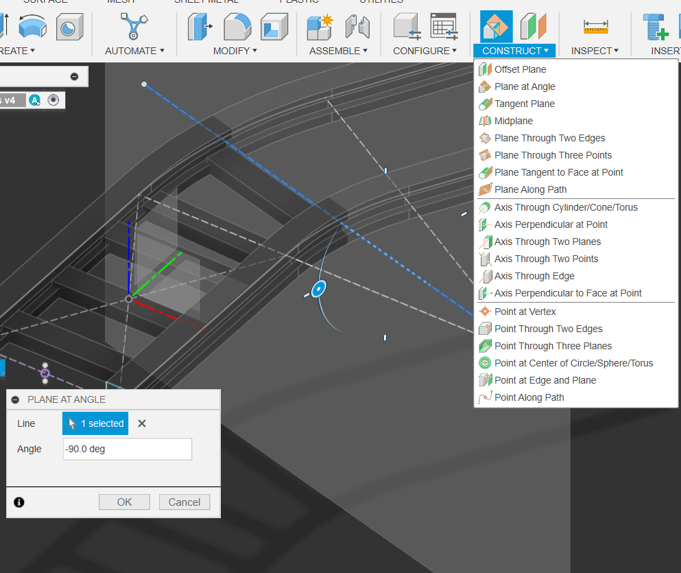
Setting Up Mirror Plane
- Select Construct, Plane at Angle
- Set angle to -90. This will serve as our mirror plane
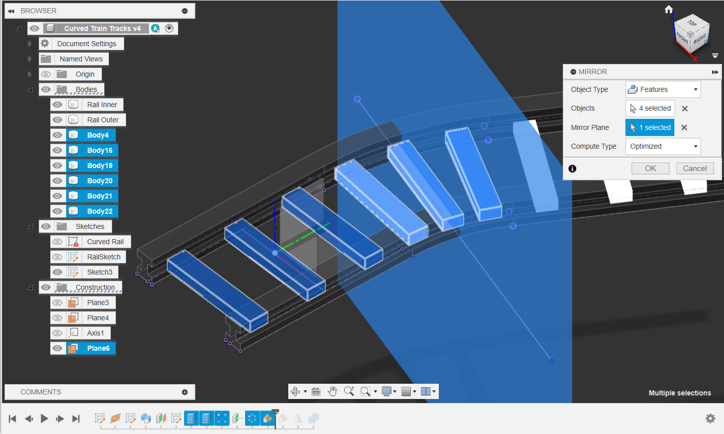
Mirroring Features
- First Select Mirror, Set Object Type to Features, Compute Type to Optimized
- Select Mirror Plane as the one we just created
- IT IS ALWAYS MORE EFFICIENT TO MIRROR/PATTERN ECT. FEATURES INSTEAD OF BODIES, & COMPUTE TO OPTIMIZED
- Select the features from the Timeline!
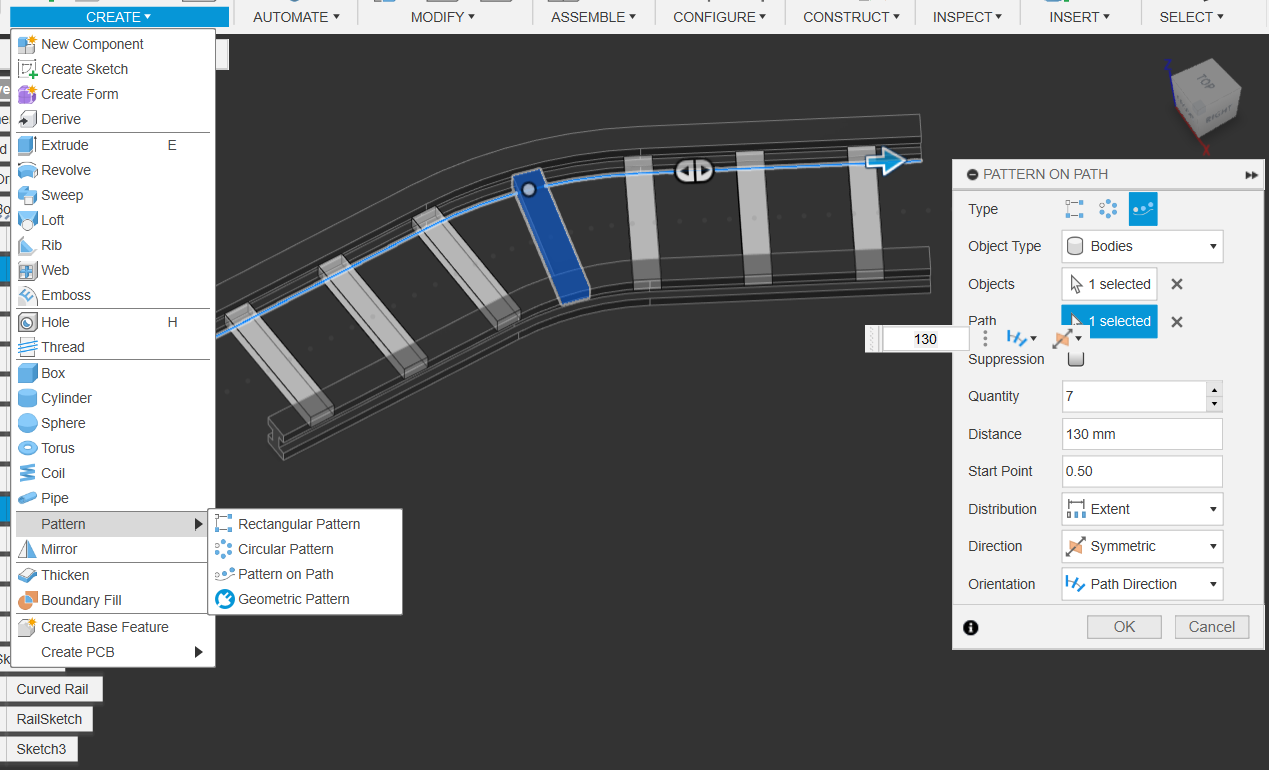
Now why did we go through all that?
- Why did we go through all that when all we had to do was use pattern on path?!?!?!
- Because it’s important to know that there’s no right way to solve a problem using CAD
- But there is a faster way!!!
- But there is a faster way!!!
Select All Bodies & Combine
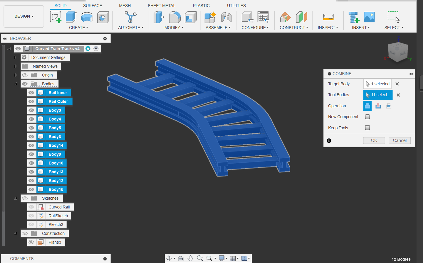
Congratulations! Your Railway is complete
- And due to the magic of parametric modelling, you can always change the dimensions through the parameter menu after the fact