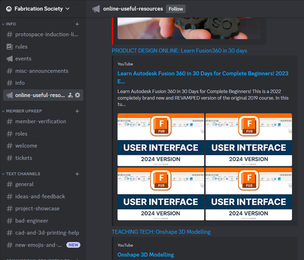
Check out #online-useful-resources! in our discord for useful links to start your deep diving in!
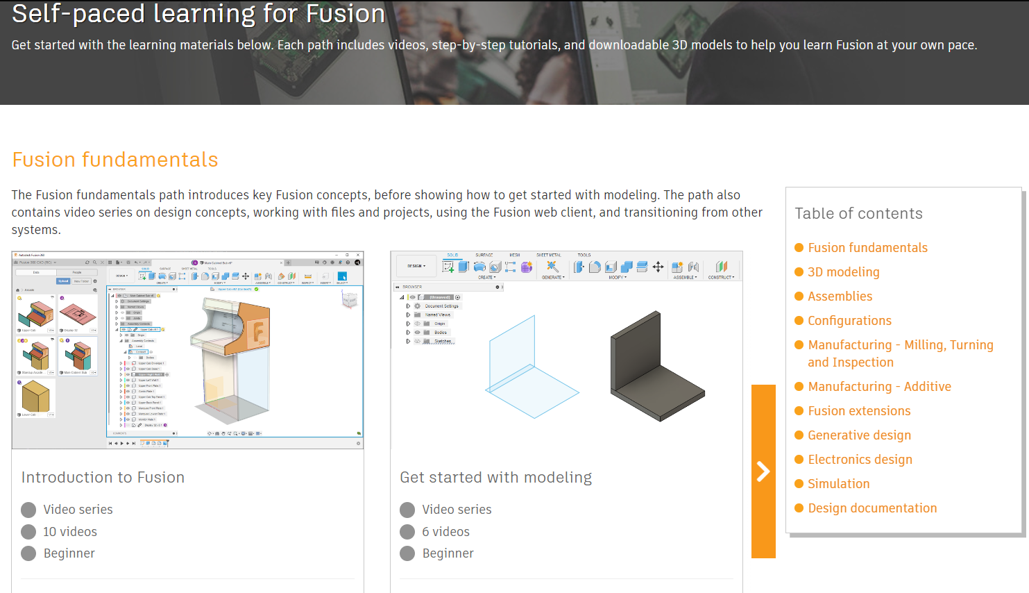
Fusion Help | Self-paced learning for Fusion | Autodesk
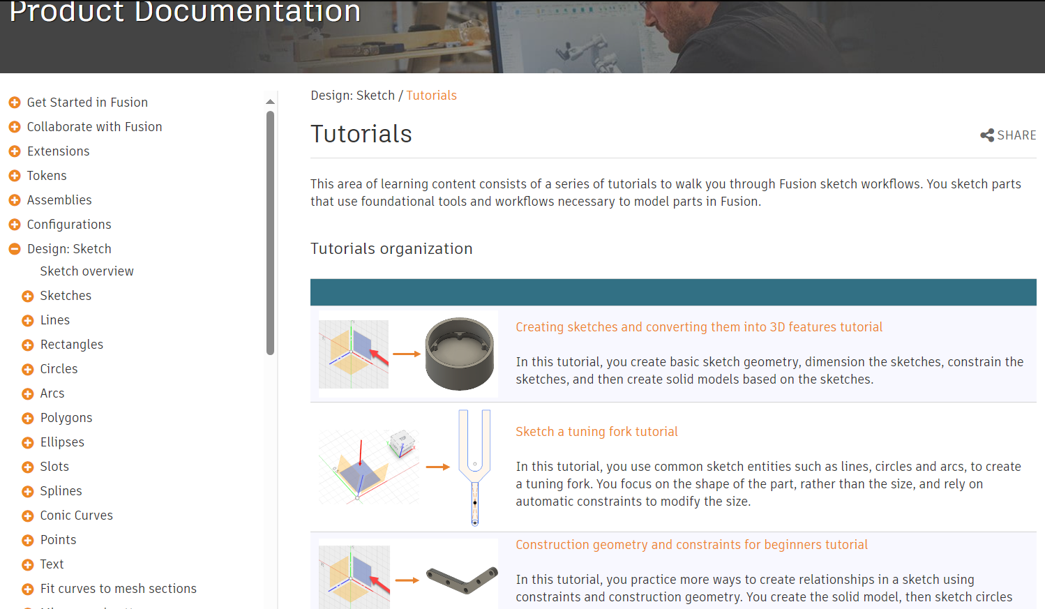
Fusion Help | Tutorials | Autodesk
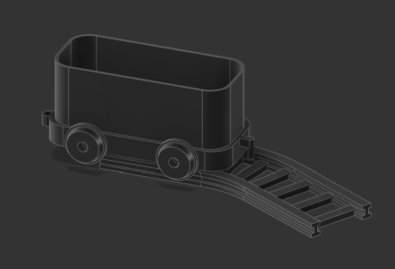
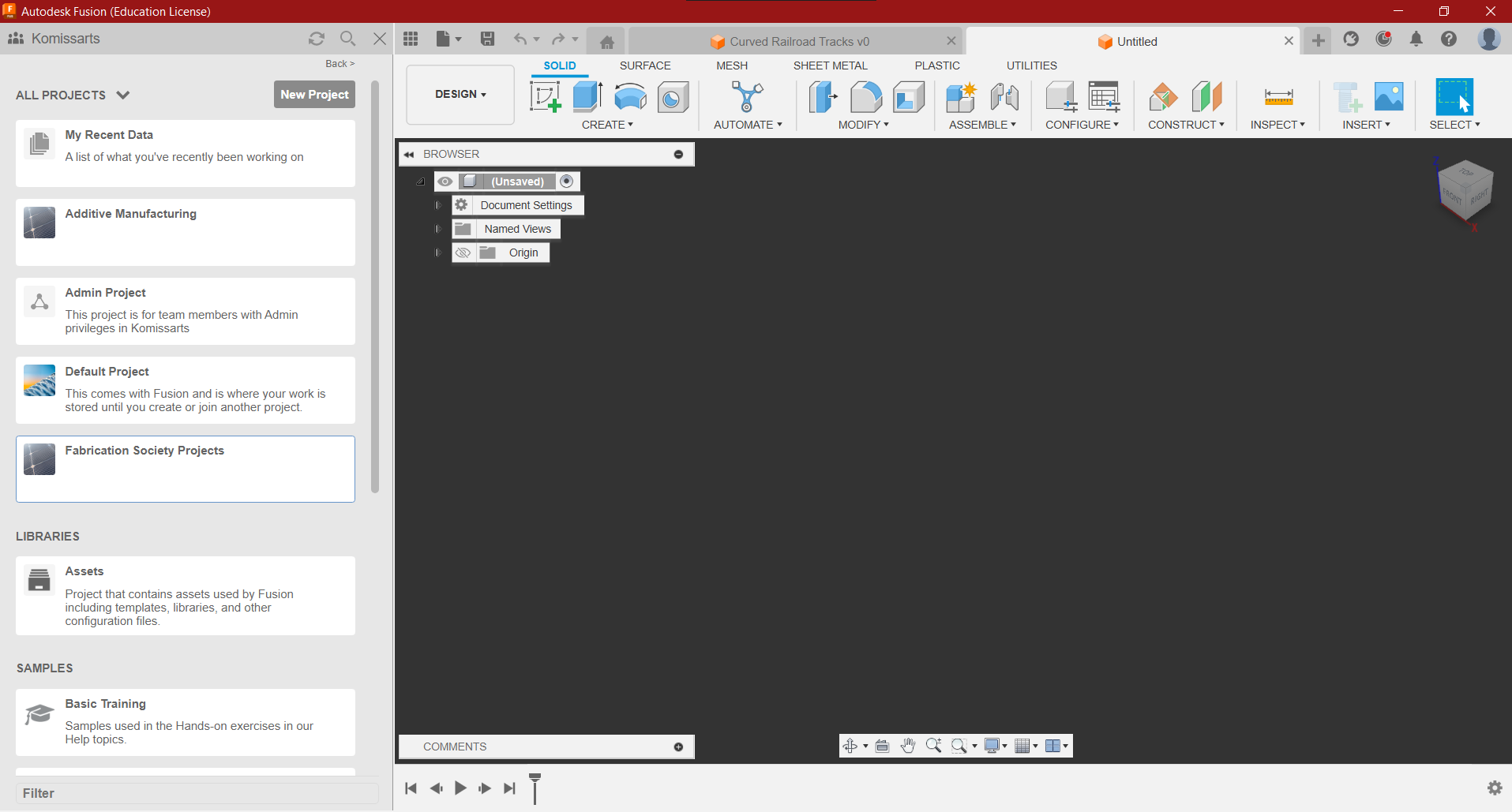
Today’s project:
Fusion 360 Home Page
- Left - Teams you are in, Project Files & Folders
- Right - Blank Workspace
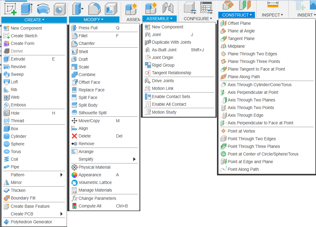
Object Modification Tools
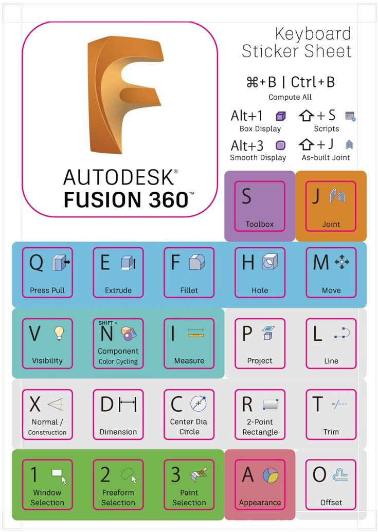
0.1.1 Rapid Fire Crash Course: Fusion 360 Interaction & Keyboard Shortcuts
Autodesk Fusion Keyboard Shortcuts, Hotkeys & Commands Guide | Autodesk Fusion360 Top 5 Shortcuts
- Pan: ctrl/alt - Middle Mouse
- Orbit: shift - Middle Mouse Button
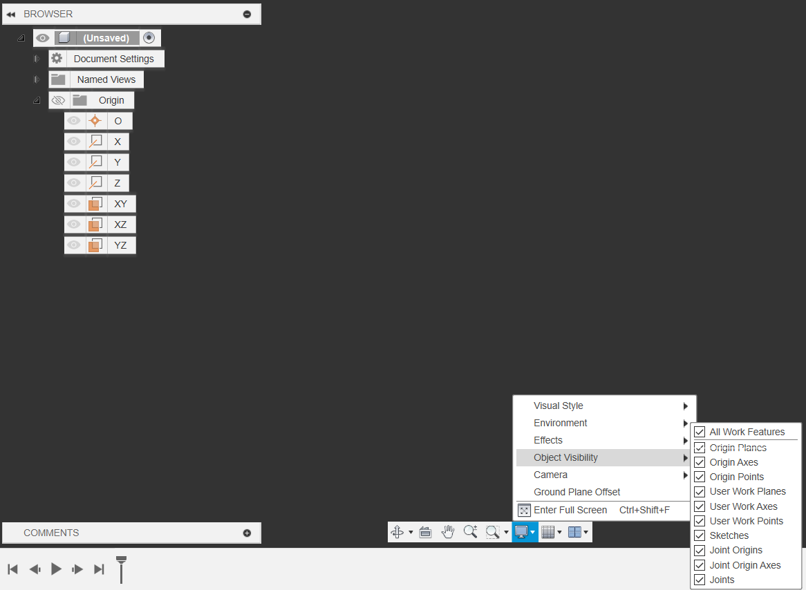
- Object visibility can be toggled by pressing on the eye icons on the left of the folders & items
- Additional Object visibility can be accessed from the bottom toolbar → Object visibility.
- Pressing on items and pressing (V) also toggles visibility
0.1.2 Rapid Fire Crash Course: Selection
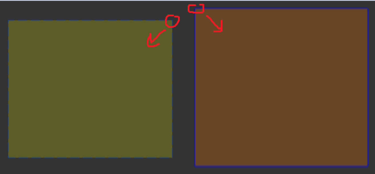
Selection in Fusion 360 is split into complete & partial selection
- Partial Selection works whenever you click and drag from Right to Left, where anything in the selection gets automatically selected
- Complete Selection works whenever you click and drag from Left to Right, where anything that is completely enveloped in the selection is selected.
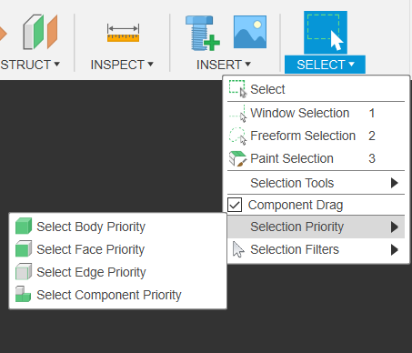
0.1.3 Rapid Fire Crash Course: Selection
- On the top right there are the selection options, allowing you to add selection filters & priorities, so you have more control over what you select
0.2 Rapid Fire Crash Course - Sketches
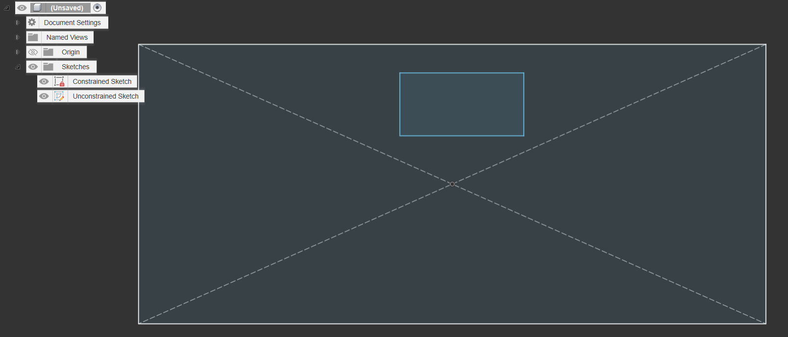
- Differences between Constrained and Unconstrained Sketches:
- Unconstrained Sketches will have elements in them that have at least 1 blue side - this means that the shape is free floating and has no associations to anything else- it is “unconstrained”
- Constrained shapes mean that every side & angle in the sketch has some relationship to something else. It might have some constraints, dimensions, or construction lines keeping it in place
- WE WANT CONSTRAINED SKETCHES (it make it much easier to edit, adjust & update using paramaters)
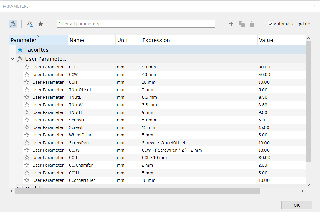
0.3 Rapid Fire Crash Course - Parameters
Don’t worry about these just yet, they’re just here for reference if you need them Parameters allow you to write dimensions, Angles and other units as mathematical expressions with a name that you can then later call whenever you use any modification commands that require some kind of numerical dimension or input i.e. most of them
- (CC = CarriageChassis) i.e.
- CCL = CarriageChassisLength
- CCIL = CarriageChassisInnerLength
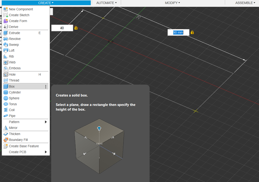
0.4.1 Rapid Fire Crash Course: Greyboxing with Primitives
- A good way to start visualizing the project we’re making is to greybox it out by using Fusion 360’s Primitives
0.3.1 Rapid Fire Crash Course: Greyboxing with Primitives
In the Dropdown Create menu shown earlier, use the Box Primitive and select the bottom plane (the red & green) to place your box. you will then be able to select a position to place it. The position does not really matter.
- Before you click to confirm placement, the dimensions text box will highlight, allowing you to type in and lock in dimensions, then Swap text box with TAB
- Dimensions will be 90x40mm & 10mm tall
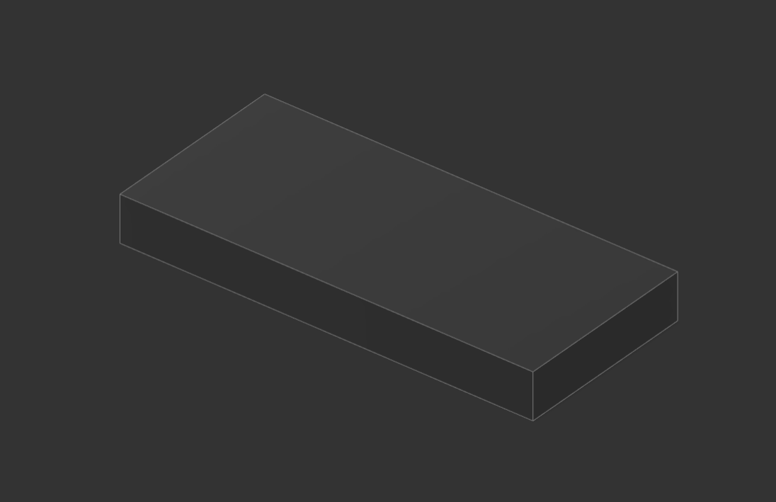
0.3.2 Rapid Fire Crash Course: Greyboxing with Primitives
- You should now have a block that looks like this
0.3.3 Rapid Fire Crash Course: Greyboxing with Primitives
- Continue, and use the box & Cylinder functions to create the rest of the wheels & cargo container
- Wheels Dimensions:
- 20mm Diamater
- 5mm Width
- Cargo:
- 80 x 30 x 20mm
Or just make your own dimensions!
- 80 x 30 x 20mm
Or just make your own dimensions!
- Wheels Dimensions:
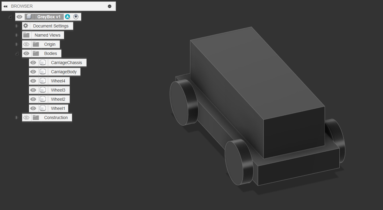
0.4.1 Renaming Bodies, Saving Files & Components
- You can right click on bodies in the dropdown menu, or slow-double click to rename bodies.
- Rename them to:
- Carriage Chassis
- Carriage Body
- Wheel 1 - 4
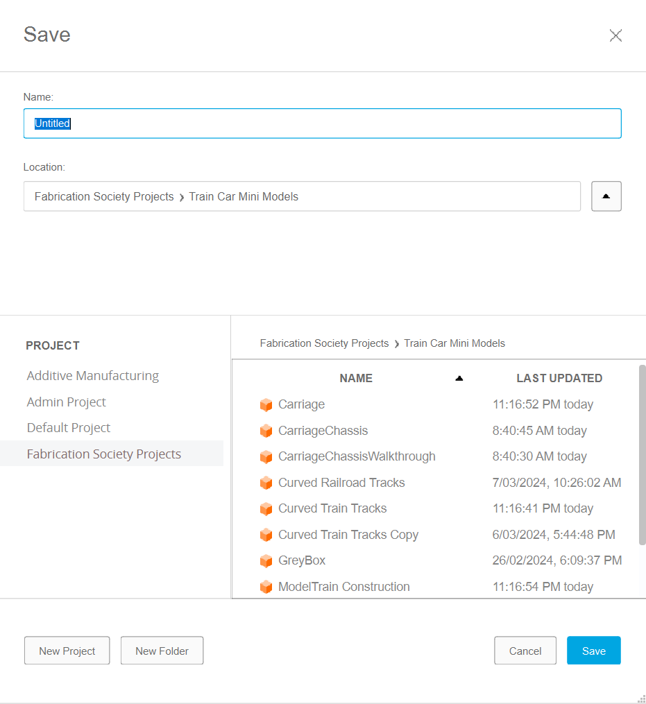
0.4.2 Renaming Bodies, Saving Files & Components
- To Save, it’s Ctrl-s or click the little save icon on the top left corner
- By saving & clicking the little triangle next to the location input box, you get the option of which Project & Folder to put it in.
- Create a “Workshops” project, and in it add a Folder called Workshop 1: Train.
- Save this file as TrainGreybox
0.4.3 Renaming Bodies, Saving Files & Components
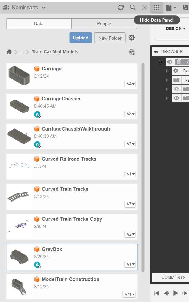
- If you open up the data panel on the top left (the 9 small squares) you can then browse your project files & folders.
- All these projects are considered “components” that can then be dragged and dropped into the project. This is very useful, and we’ll explore in more detail soon
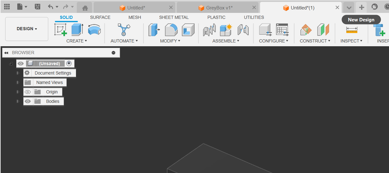
0.5 Create New File
- Simply just press the ”+” New Design on the top right
1. Making the Carriage Chassis
Creating the First sketch:
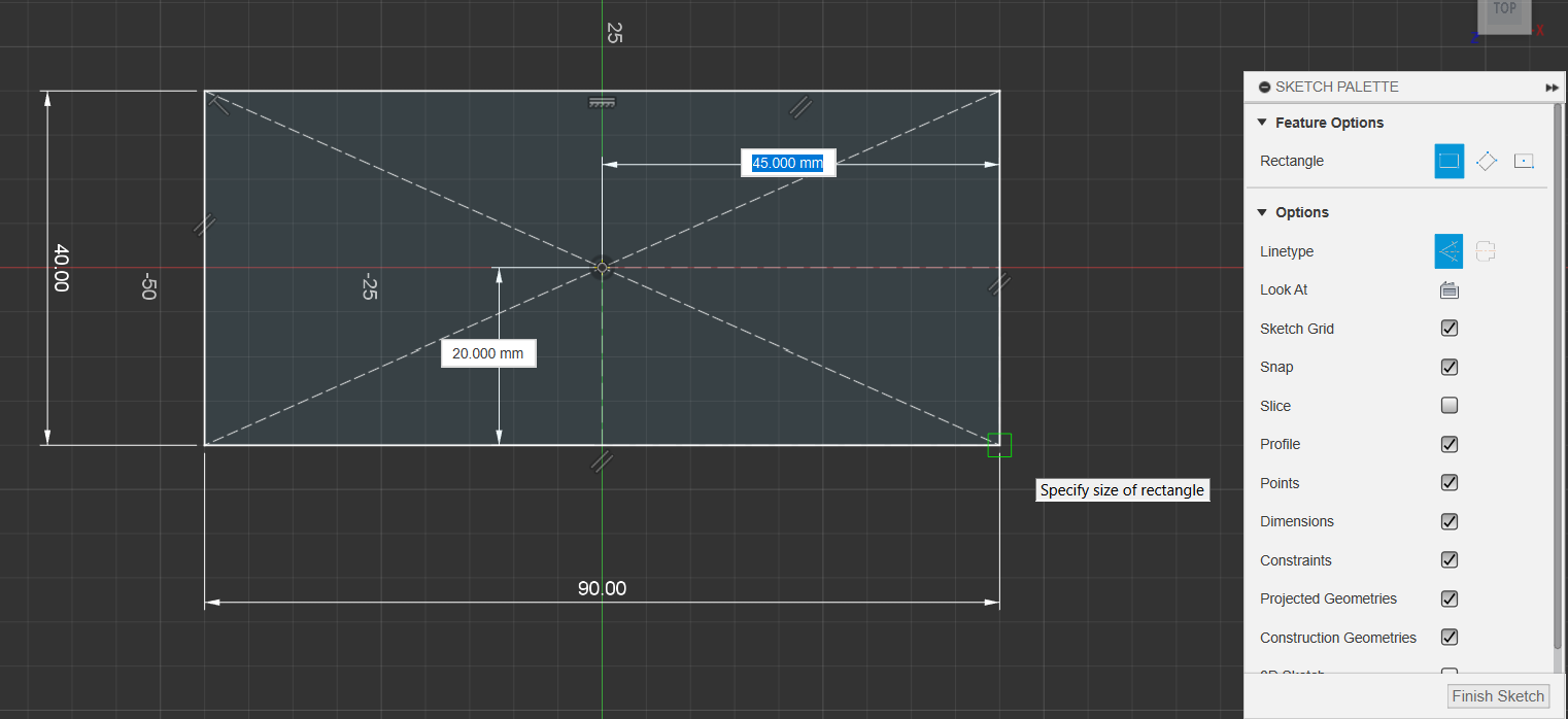
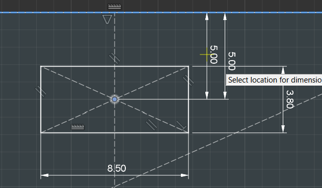
1.1. Main Chassis Rectangle
- Create a Centre Rectangle with the following Dimensions
- (Ps. when you first click to place the rectangle, you are able to type number values for width and height, toggling between both with tab)
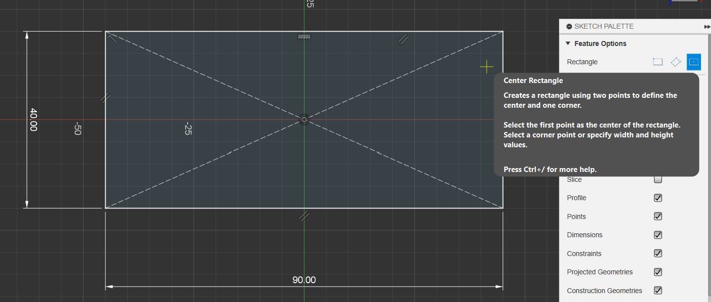
- (Ps. when you first click to place the rectangle, you are able to type number values for width and height, toggling between both with tab)
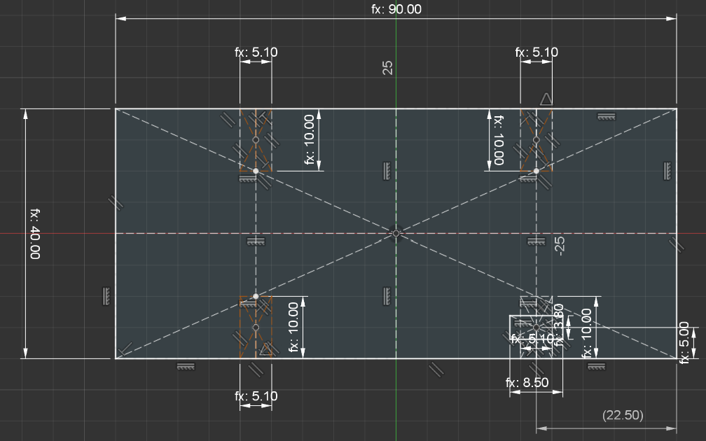
1.2. Create Square Nut Insert Hole
- Create a 2-point rectangle, starting from the centre (black) point, and click on the bottom right corner
- Ensure that the line type is selected as Construction!!
1.2.1 Create Square Nut Insert Hole
- Use Centre Rectangle (Non- Construction)
- Add a Construction line through the centre of this new Rectangle (wait until you see the triangle icon, that means it’s the midpoint)
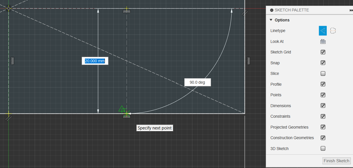
1.2.2 Create Square Nut Insert Hole
- Create another centre rectangle (non Construction)at any point along this new line, with the below dimensions
- Then press D for the dimension tool, select the Far Edge of the 1st rectangle, and the black dot of the new rectangle, and make 5 the dimension
Creating the Chassis pt.1
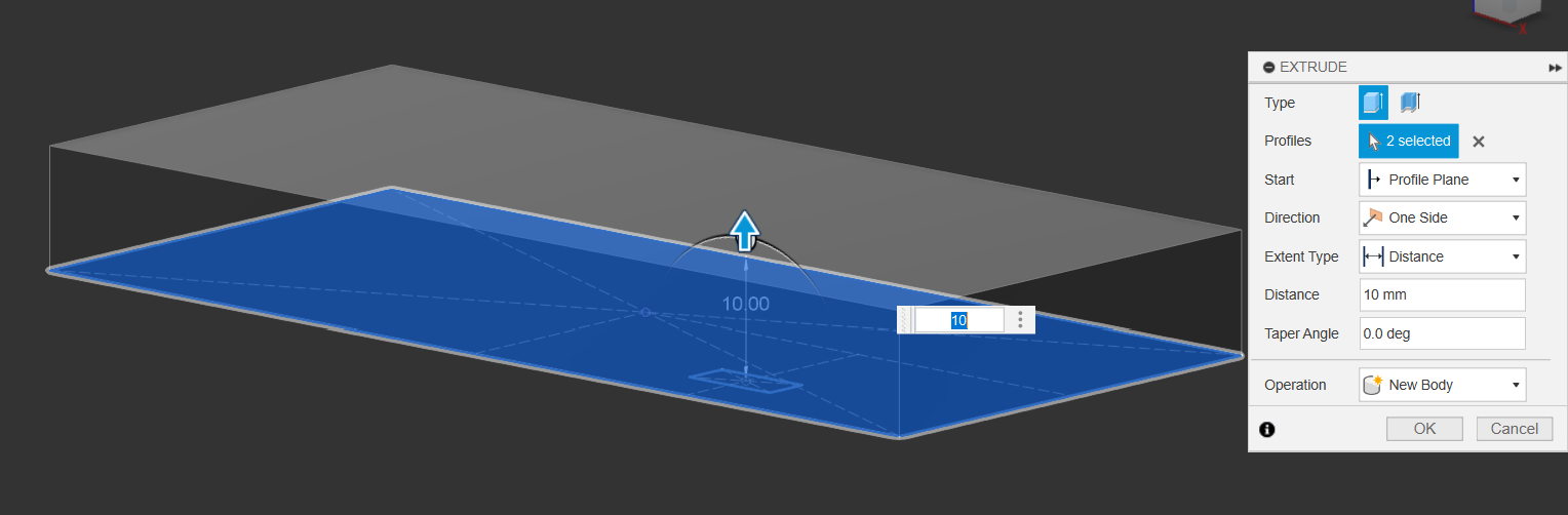
1.3.0 Extrude Main Chassis & Square Nut
- You’ll notice that there are two sections that are highlightable
- Press E(for extrude) or Q(for press pull and it’ll automatically turn into an extrude)
- Select both faces and extrude them up by 10mm as New Body
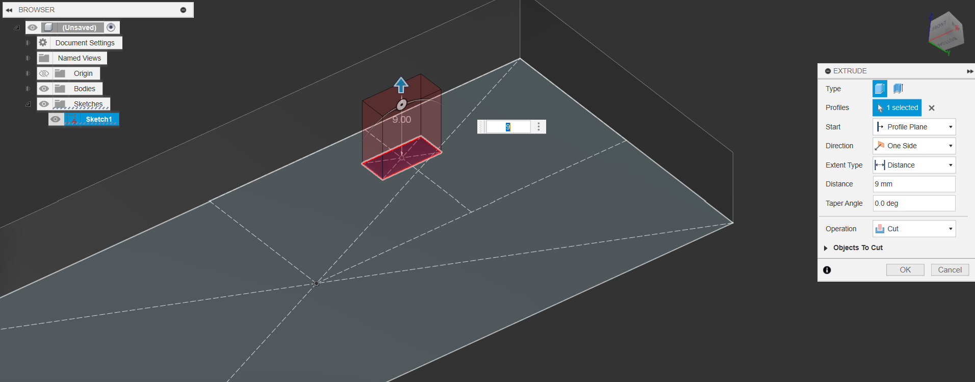
1.3.1 Extrude Main Chasses & Square Nut
- Once you’ve confirmed the extrude you’ll notice that the sketch dissapears.
- Go the the sketch folder and click on the eye to make it visible again
- Once you’ve made it visible, extrude the Square Nut hole by 9mm
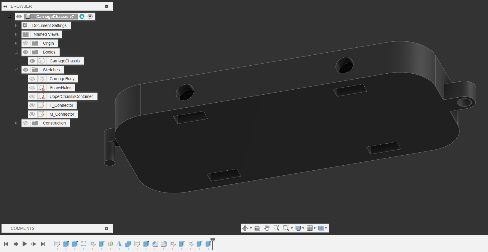
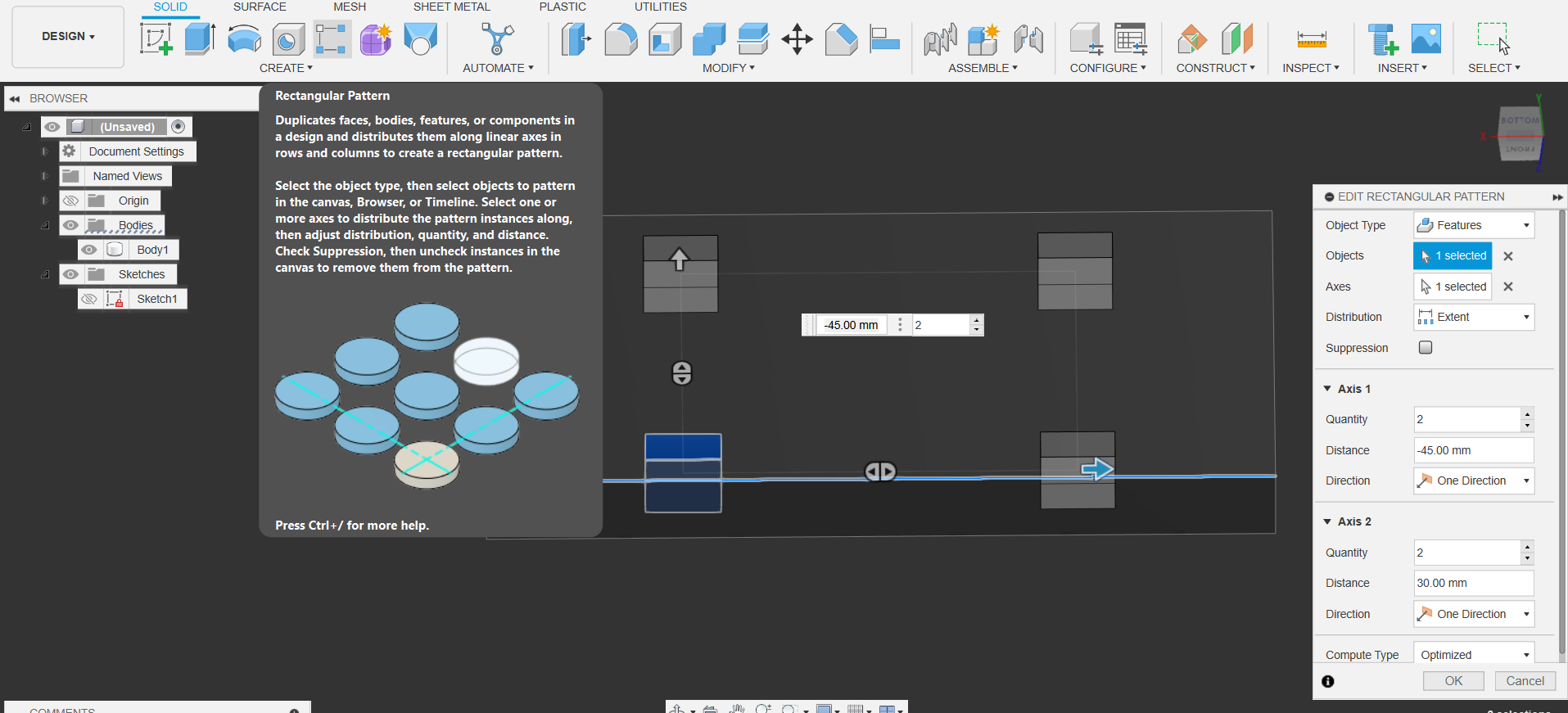
1.4. Rectangular Pattern the Square Nut Feature
- Use the Rectangular Pattern set to object type features, to pattern that extrude command we did across the bottom of the body.
- We select the long edge of the body as the axis, and the extrude feature as the object.
- Copy the values below to get a similar outcome
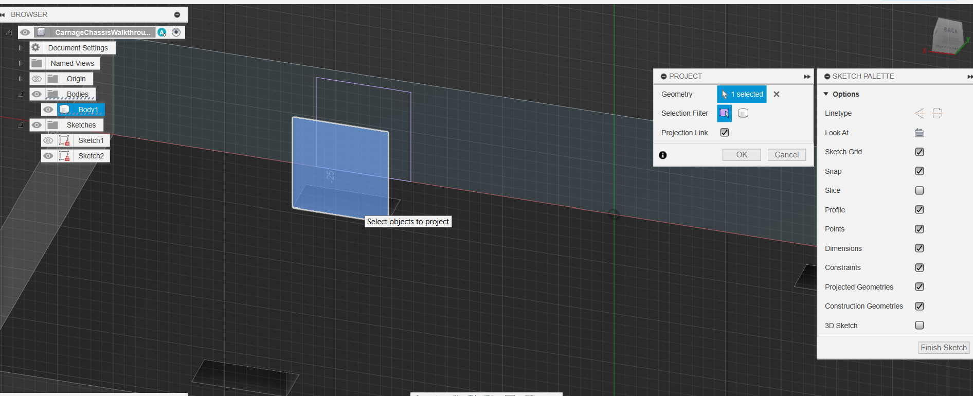
1.5. Creating the Screw Hole Axles
- Start a new sketch on the side of the main block
- Press P to create a project command and project the inside of the extruded slot.
- Double click on the line of this new rectangle and press X to turn it into a construction line
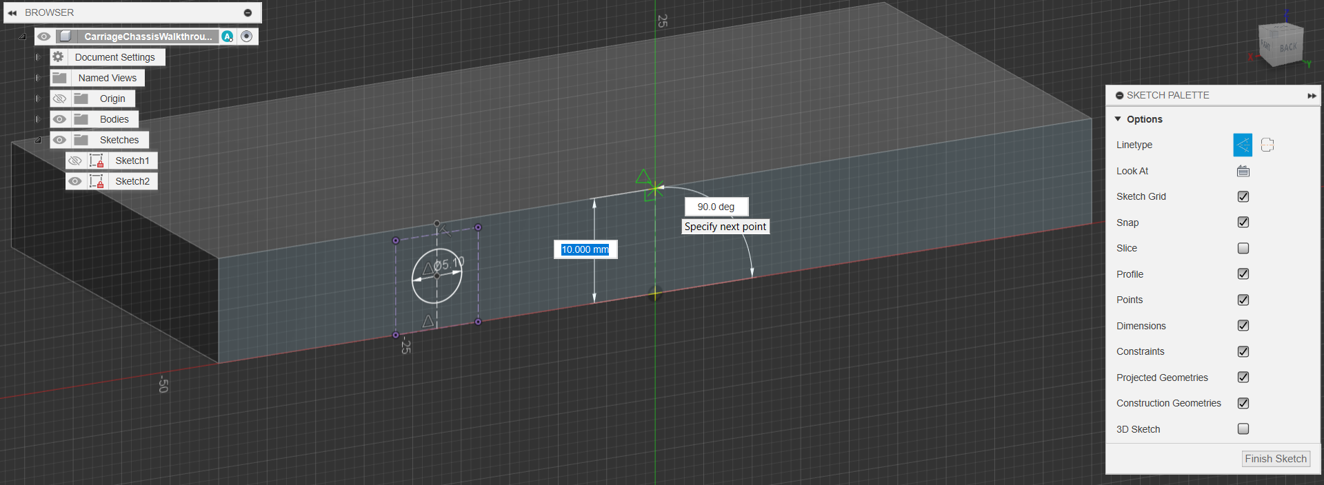
1.5.1 Creating the Screw Hole Axles
- Now, all we want is the centerline to create a hole so we can insert the screws to act as an axle
- Press L to activate the line tool, and create the line through the side, using the midpoint guide(remember the triangle symbol), and turn it into a construction line.
- Then add a Diameter Circle at the midpoint of this new line

1.5.2. Creating the Screw Hole Axles
- Create another construction line down the middle of the block side
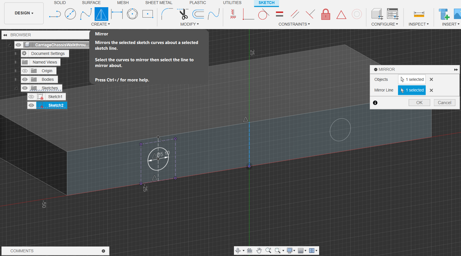
1.5.3. Creating the Screw Hole Axles
- Use the Mirror tool to mirror the Circle we made across the construction line we made in 5.2
- Finish Sketch
1.5.4. Creating the Screw Hole Axles
- Use the extrude tool and circles we made, extrude them 10mm in, cutting into the chassis block
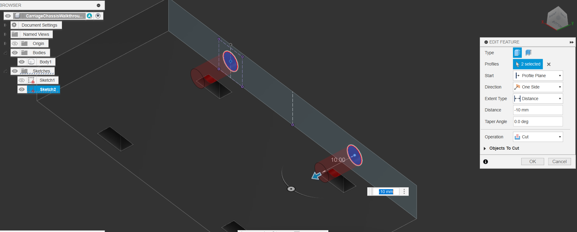
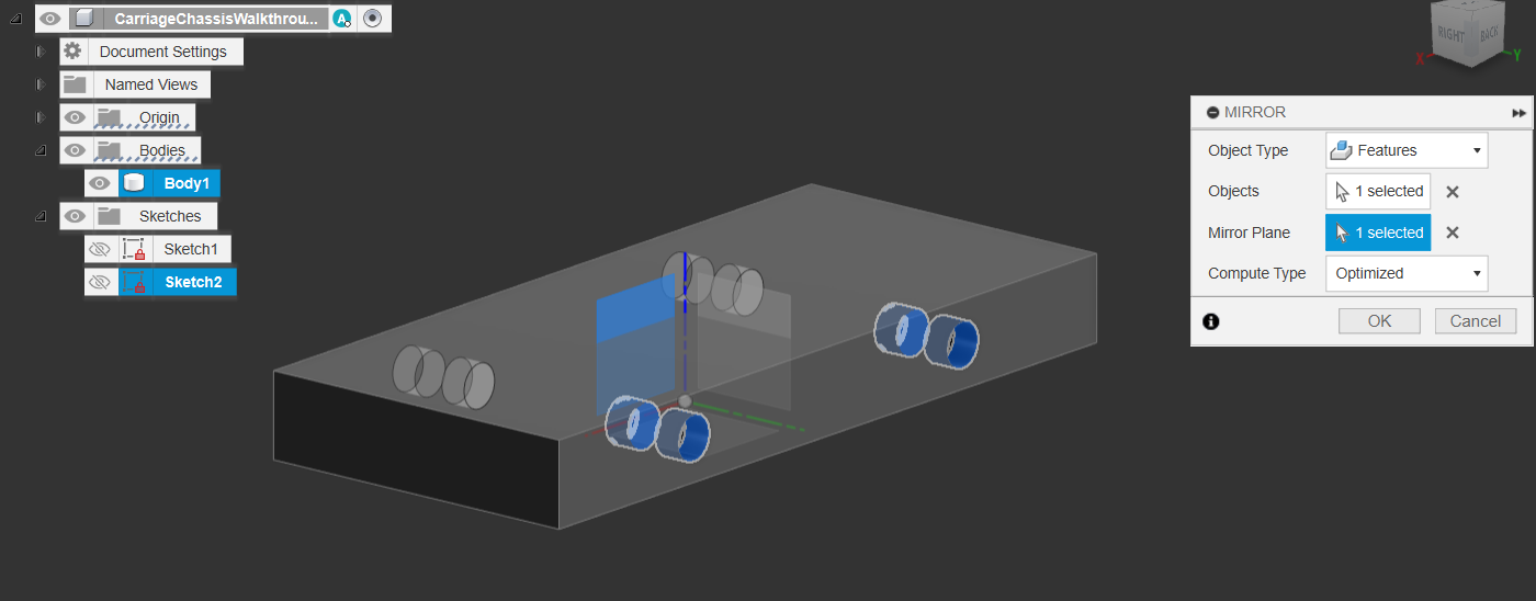
1.5.5. Creating the Screw Hole Axles
- You may have noticed that the origin folder has been made invisible, toggle it’s visibility by pressing the eye icon. This will show the Origin Planes, Axis & Point
- Use the Mirror tool set to Feature & Optimized to mirror the Extrusion features we just did, using the axis plane as the mirroring plane
- It’s always better to mirror & pattern features, insteaad of faces & bodies
- It’s always better to mirror & pattern features, insteaad of faces & bodies
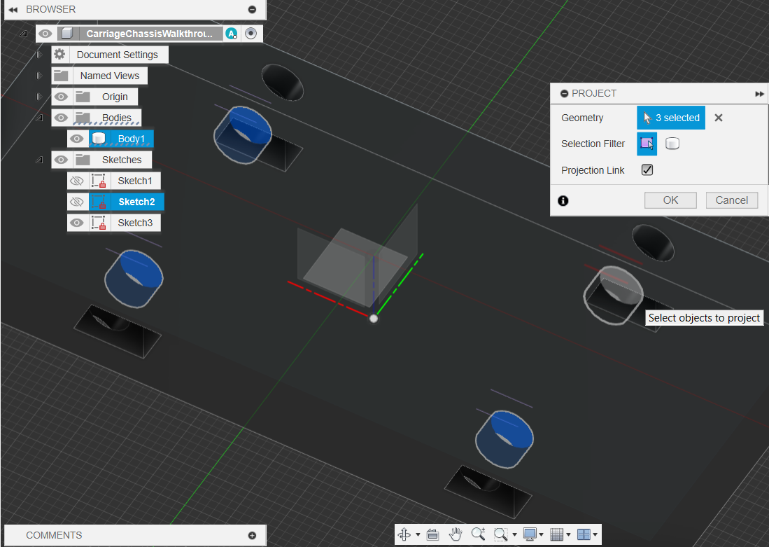
1.6.1. Creating Chassis Container Slot
- we will now create a little slot to mount the Container into.
- Select the top plane, and create a sketch.
- Use the (P) project tool to project the inner cylinders from the previous extrusion.
- This is to allow us to know where to avoid cutting into
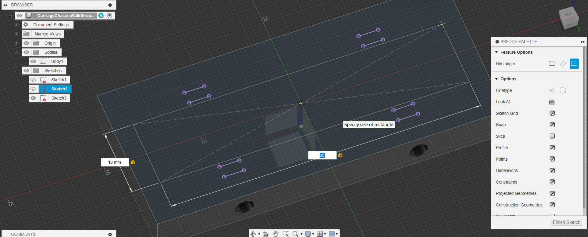
1.6.2. Creating Chassis Container Slot
- Again, create a center rectangle with the dimensions:
- 18x80mm
- Finish Sketch
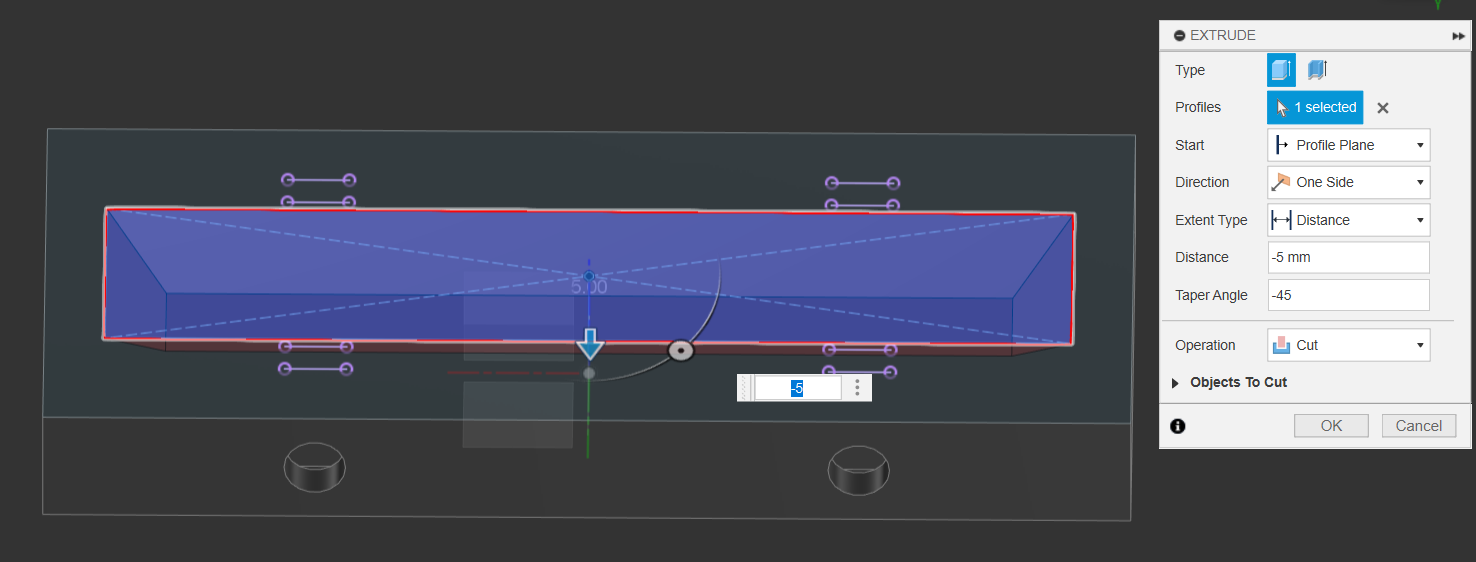
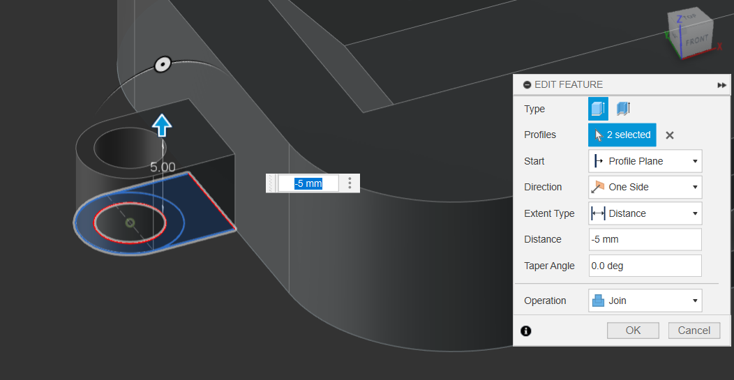
1.6.3. Creating Chassis Container Slot
- Extrude this new rectangle 5mm into the body
- Add a taper angle at -45mm
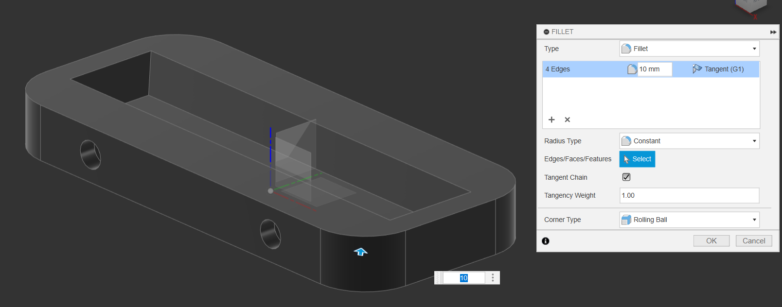
1.7. Clean Up the Corners
- Using the fillet or Chamfer tool, round out or chamfer the corners of the chassis
- 10mm is a good distance
- 10mm is a good distance
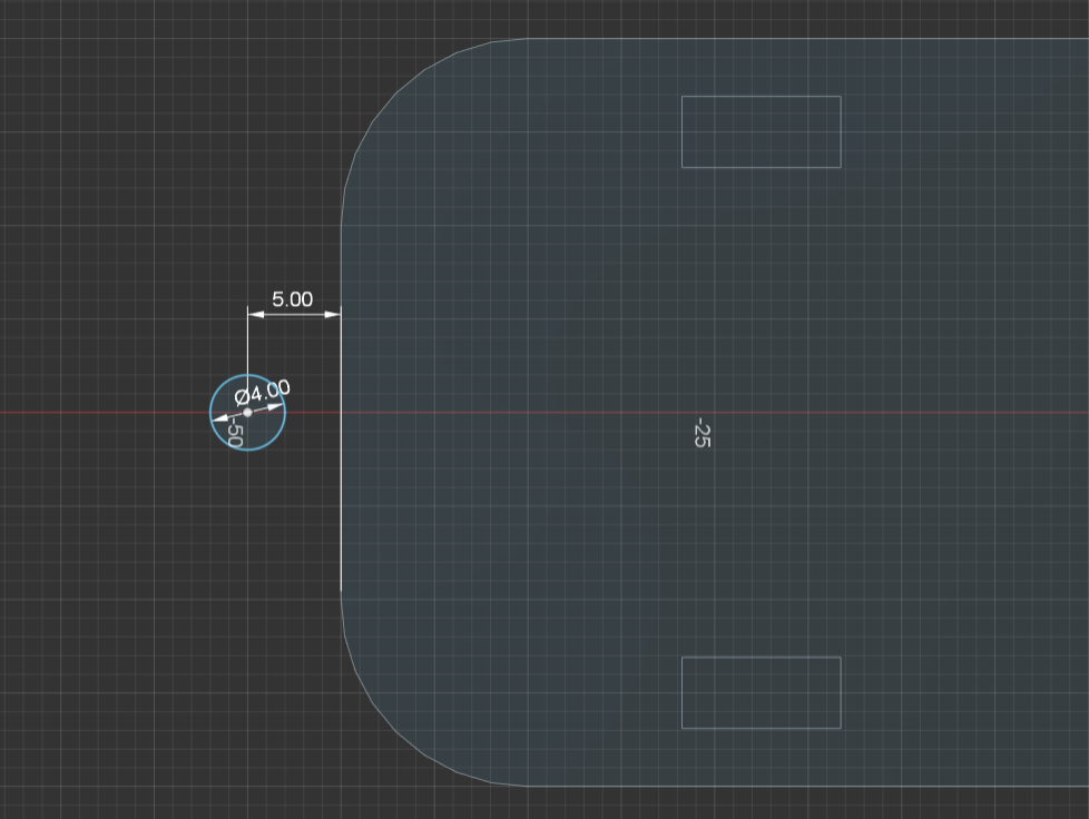
1.8.1. Making the Male & Female Connectors
- Create a sketch on the bottom of the chassis, and add a 4mm circle along the centerline of the bottom, 5mm from the end. (Remember to click on the inner circle point, not the outer diameter!)
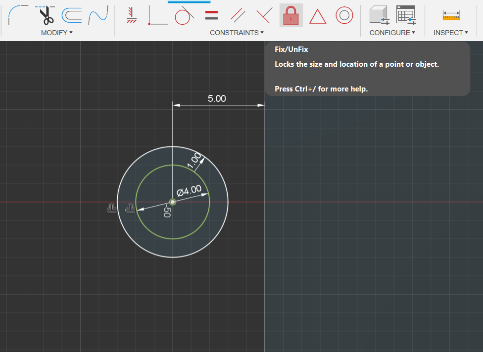
1.8.2. Making the Male & Female Connectors
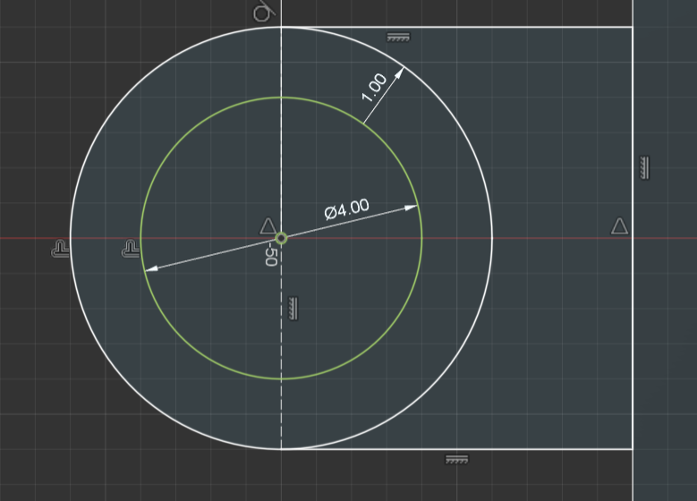
- Use the Offset tool to offset the circle by 1mm
- Use the Fix/Unfix Constraint to fix the center Circle in place. It should now be green
1.8.3. Making the Male & Female Connectors - Constraints
- We will be using the following Constraint commands: Tangent & Midpoint Constraint.
- Create a floating 2-point rectangle, then use the Midpoint Constraint to constrain it to the midpoint of the main chassis body
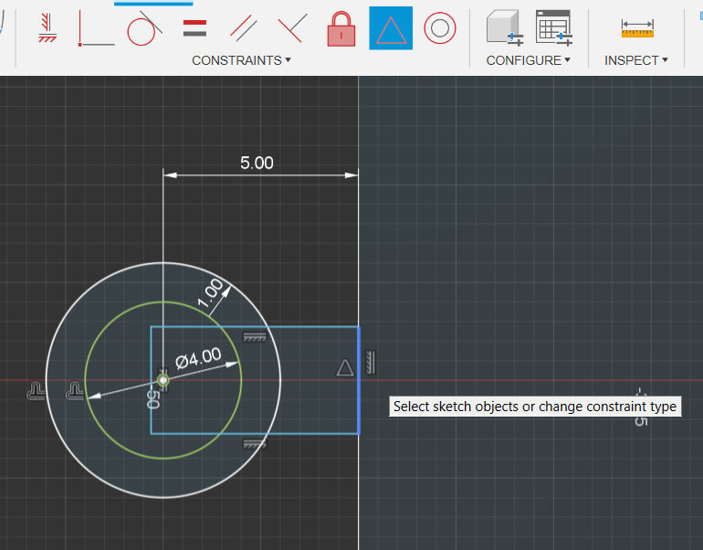
1.8.4. Making the Male & Female Connectors - Constraints
- Repeat above step & constrain the other side of the rectangle to the midpoint of the circle (the little white/green circle)
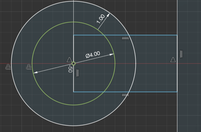
1.8.5. Making the Male & Female Connectors - Constraints
- use the Tangent Constrain to constrain the top and bottom sides of the rectangle to the outside circle
- Select the line that goes down the middle of the circles & toggle it to be construction
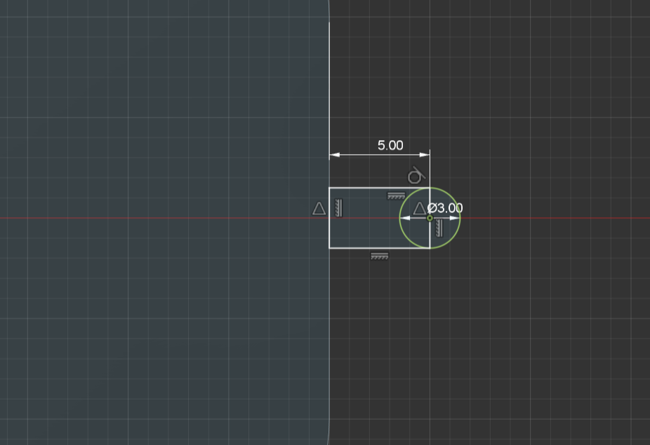
1.8.6. Making the Male & Female Connectors - Male Connector
- Functionally repeat the above steps,
- On the opposite side of the Chassis, add a 3mm diameter circle along the midline, 5mm away from the chassis. Fix it in place
- Create a floating rectangle and & midpoint constrain it to the chassis & the circle
- Tangent Constrain it to the circle
- Constructify the rectangle’s line that cuts through the circle
- Finish Sketch
1.8.7. Making the Male & Female Connectors - Extrusion Shenanigans
- Returning back to the Female Connector- simply extrude it up by 5mm
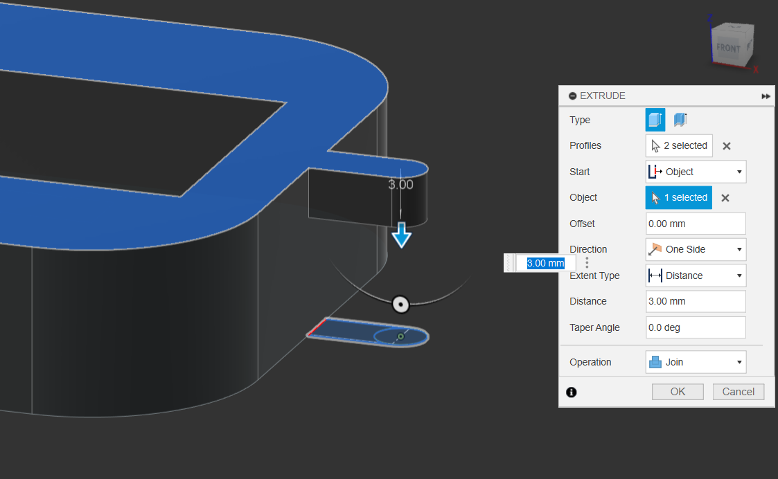
1.8.8. Making the Male & Female Connectors - Extrusion Shenanigans
- For the Male Connector, select the rectangle & circle, but change the Start setting to “Object”.
- Then select the top surface & extrude by 3mm
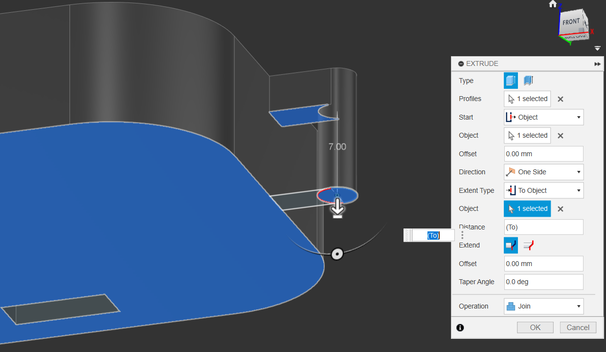
1.8.9. Making the Male & Female Connectors - Extrusion Shenanigans
- For the Protruding Pin, you’ll have to do something similar, Setting the start surface to the extruded face we just made
- Se the Extent Type to object & select the bottom face
1.9. A Quick Tangent on the Extrude Function
The Extrude Function is the most useful tool you will ever encounter. It has an incredible amount of input parameters - setting start & end locations, Taper 7 Offset angles, Cut, Join, Intersect type; Single side, Symmetric or differing distance extrudes. It is strongly recommended for you to play around & get used to the different uses the Extrude function serves
1.10. Save Completed Chassis
- Save the completed Chassis & Open a new Design.
2. Creating the Wheels:
2.1. Extrude some more? NO - we using revolve now
- There are many ways to tackle this problem, the simplest coming to mind being making some simple sketches, extrudes and chamfers
- Instead - we shall be exploring the Revolve feature!
- We’ll explore making the wheel with Extrude first, and then we’ll start again to re-create it using revolves.
- We’ll be making the revolve a bit more challenging and more complicated than it needs to be, so feel free to follow along with the extrude before we tackle the revolve
2.2.1 Extrude Timeline
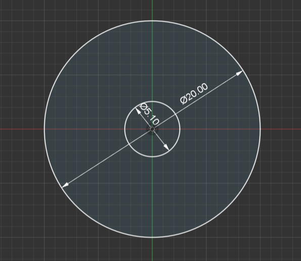
- In your new design, create a sketch with two circles in the center, one at 5.10mm, and another at 20mm.
- Finish Sketch
2.2.2. Extrude Timeline
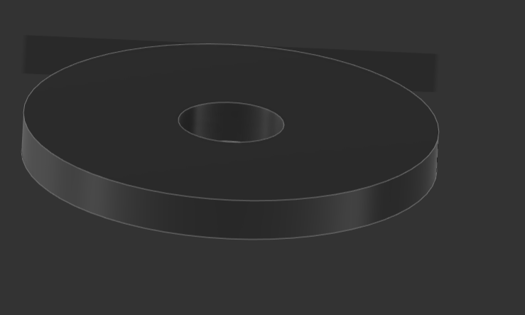
- Extrude the outer circle by 2mm
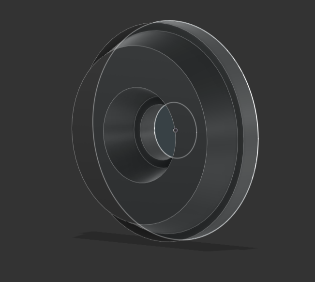
2.2.3. Extrude Timeline
- Re-use the sketch & reselect the outer face again, extrude by 5mm with a 20 degree Taper
2.3.1 Revolve Timeline
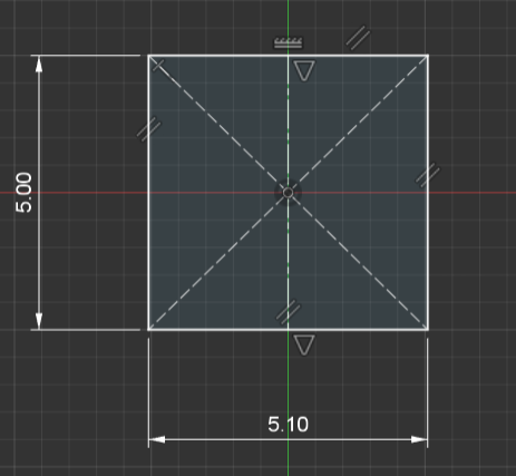
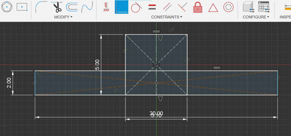
- Create a center rectangle of 5 x 5.10
- Use the line tool set to centerline to cut the new rectangle in half
2.3.2 Revolve Timeline
- Create a larger rectangle, 2mm x 20mm floating somewhere on the green line, so it’s automatically constrained to it.
- Use the Coincident Constraint to snap the new rectangle to the bottom of the rectangle
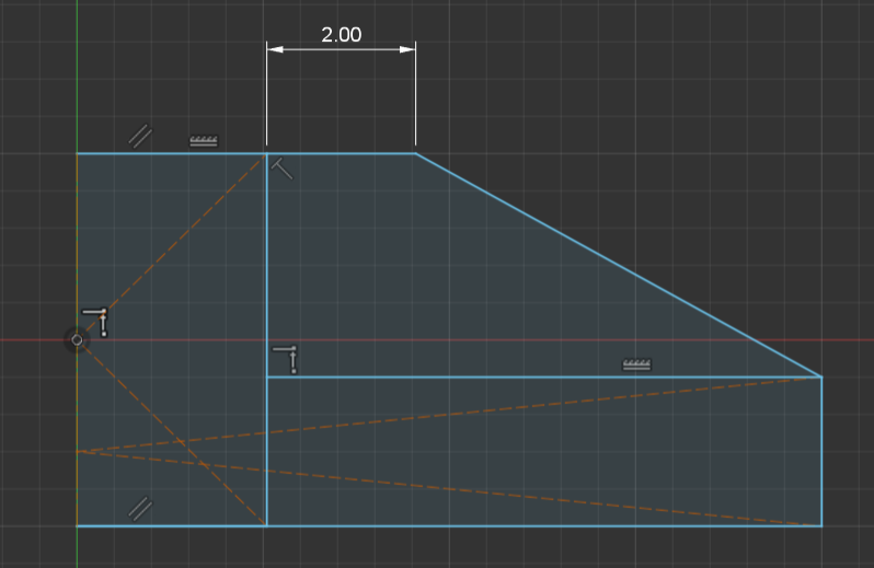
2.3.3 Revolve Timeline
- Press (T) to enable the trim tool, and just click and drag to remove all the lines to the left/right of the shapes.
- Add the slope/chamfer 2mm from the center & slope it down to the edge
- Go nuts with this, have fun and make it all kinds of wacky
2.3.4 Revolve Timeline
- Clean up the outsides, as the original rectangle was the hole where the screw goes through
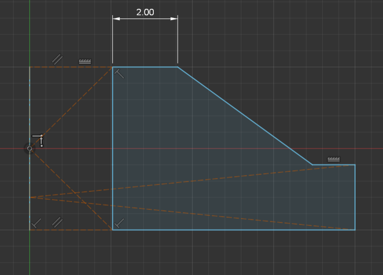
2.3.4 Revolve Timeline
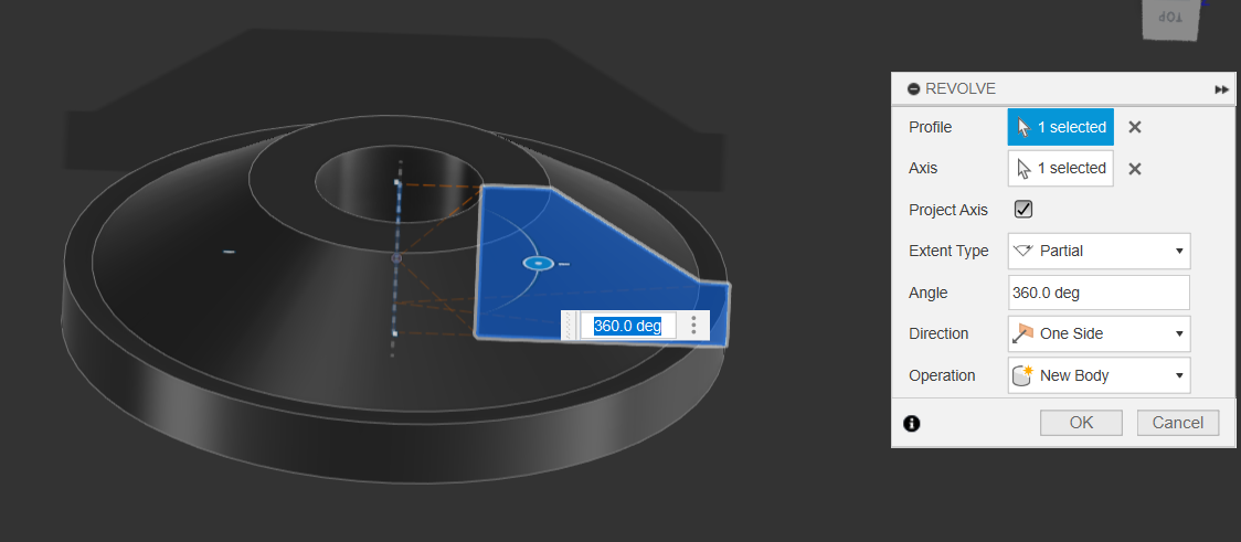
- Finish Sketch & use the revolve tool for the sketch face
2.3.5 Complete & Choose your preferred wheel
- Choose your preferred wheel by just turning off the visibility of the other one
- Save your project.
3.1. Linked Components, Assemblies & Joints
- Now that we’ve completed the Chassis & Wheels, we’re going to explore how to combine these two elements in an Assembly workspace
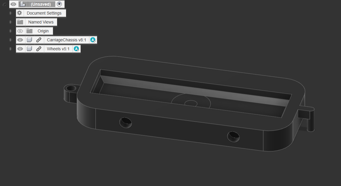
- Open a new tab, and open your Data panel to the project & folder that you saved your wheels and Chassis into.
- Drag and Drop the two files into the blank workspace
- You’ll notice that the two components have a chain link icon next to them.
- This means that they are external components that are linked & automatically updated whenever you change the original files. This allows you to make adjustments to either parts & the assembly
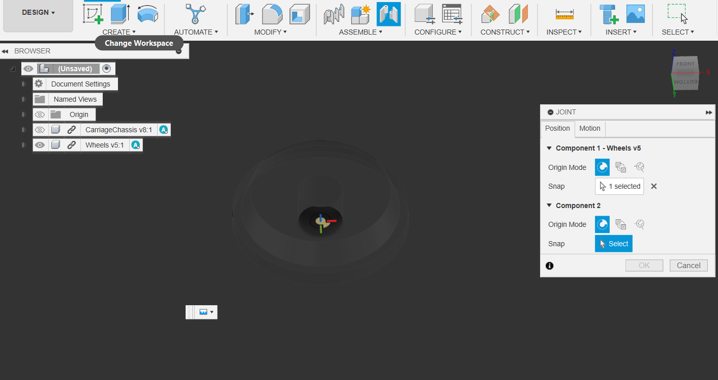
3.2 Adding Joints
- Disable Visibility for the Carriage and use the Joints Tool on the inside wheel
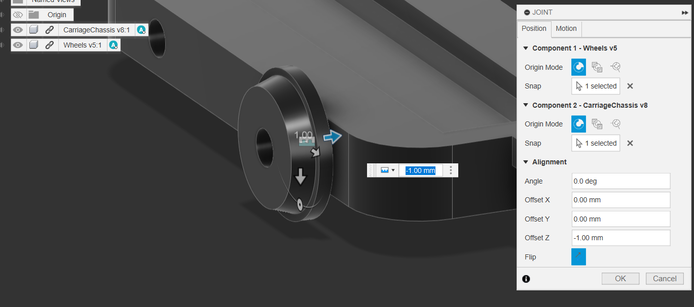
3.3 Adding Joints
- Enable Visibility for the main chassis & select the center of the Chassis’ Axle hole.
- Add a 1mm buffer
- Repeat the import & Joint attachment of the wheels 3 more times
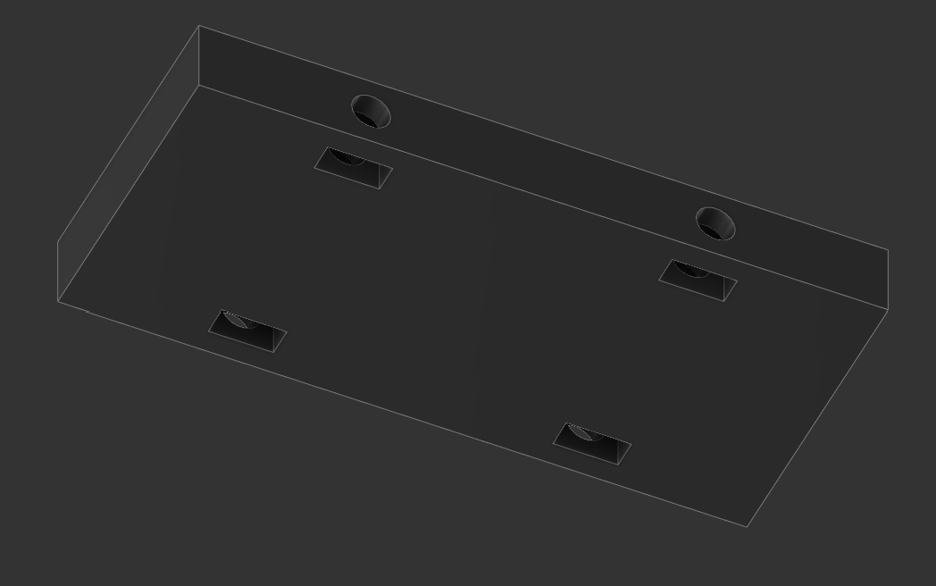
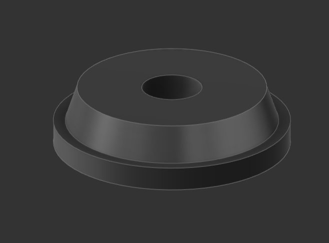
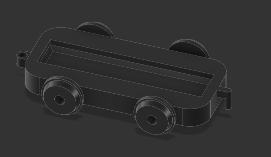
4.0 Congratulations!
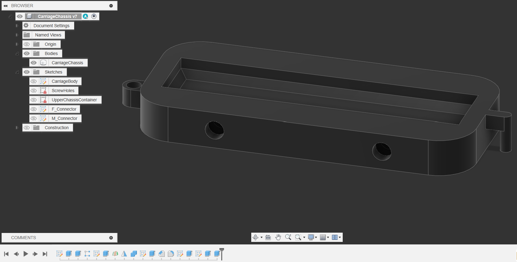
- Congrats, by now you should have something that is similar to this!
- For the rest of the workshop, use the techniques and workflow you’ve learnt to create a container to stick on top of the chassis!
Finished? Advanced CAD Challenge: Check out CAD Workshop 0.5 and test your skills making a parametric Train Rail
Next Workshop: 101 3D printing & optimizing for 3D Printing
- Learn how to